www.miinet.com Moore Industries-International, Inc.
- 52 -
User’s Manual
225-748-00P
August 2024
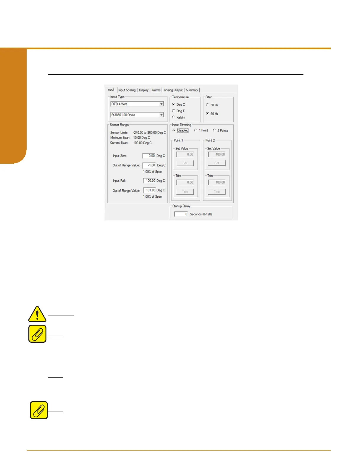
Figure 5.1. Input Tab
Input Type– Select your input type and the respective range of your input.
Temperature– If a temperature mode has been selected, use this section to select the unit you
wish to view.
Filter– This setting is used to configure the input filter. This filter is designed to reduce the effects
of mains-induced noise. The input filter frequency value should be set to the frequency of the
local AC supply– either 50Hz or 60Hz.
Sensor Range– Allows you to set your Input Full and Input Zero values within the range chosen
in the Input Type section. The desired Input Full and Input Zero settings can be entered via your
PC keyboard. The Out Of Range settings can also be entered via your PC keyboard.
Warning: The default value for INPUT OOR is 1% current span. For safety applications, the
INPUT OOR value must be set to 2% or less.
Note: Entered Values must be within the displayed Sensor Limits. If an entered value falls
outside the Conformance Range a warning will be displayed below the eld. Minimum Span is
also displayed and Span between entered values must conform to this minimum value. Refer
to Table 9.4 for Sensor Limits, Minimum Span and Conformance Range for each specic Input
Type.
Note: The actual physical value must be entered in the Out Of Range elds, percentage is
automatically displayed below this eld. Values entered in the Out Of Range elds for the Input
Full and Input Zero are limited 0% to 5 % of the Current Span. Current Span is displayed above
along with Sensor Limits and Minimum Span.
Note: For STA units with rmware versions 1.5 and earlier, OOR is not congurable and the
value is set to 1%.
Input
Programmable RTD, T/C, Ohms, mV and Potentiometer Safety Trip Alarm
STA
TPRG
SECTION 5