Installation
15
Brake Resistance; DC Brake Only
Large resistors with slip-ring adjusters are used to adjust brake drop time. Resistor
RB1 adjusts primary brake output. Resistor RB2 adjusts the auxiliary brake output.
Check sheet -1 of your job prints for detailed information.)
1. Check the resistance across RB1 and RB2. As an initial working value, RB
resistance should be about three times (3 X) the resistance measured across
the brake coil.
2. Adjust RB1 and RB2 as required.
Wiring the Brake
1. Refer to the job prints. Connect brake wires to controller terminals B1 and
B2.
2. Connect aux brake wires to controller terminals EB1 and EB2 (if available).
3. Brake wires must not be routed in the same conduit with AC motor wires or
velocity encoder wires.
Safety String
Safety string devices are wired in series between a 24VDC source and the #4 bus in the control-
ler. The #4 bus is connected to the safety inputs of the main and secondary processor boards
(P6 on the EC-MCB and P26 on the EC-SCB).
1. Refer to the drawings package for the job.
2. Connect the safety string as shown.
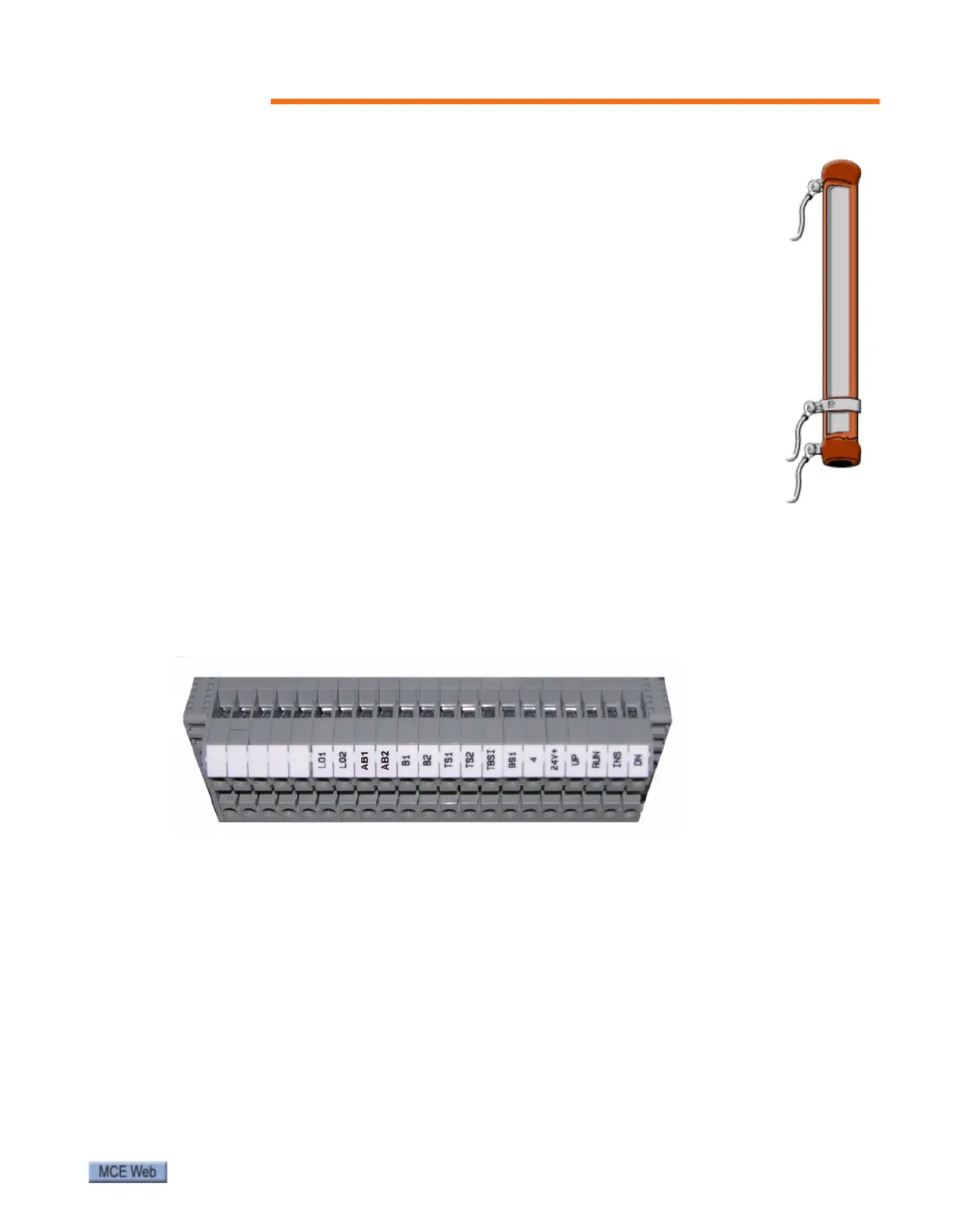
Figure 1. Typical Controller Terminal Block
Auxiliary Brake Information
If your job uses an auxiliary brake (usually mounted with the step drive equipment and not pro-
vided by MCE), it will stay picked until one of four conditions occur:
• Loss of power
• Step overspeed faults occur (E-02, E-03, E-40, E-41)
• Step reversal faults occur (E-01, E-39)
• Drive chain broken detection device input activated (error E-19, input P19)