Brake Module
71
CAN Control Adjustment
1. Apply power to the controller. Place the escalator on Inspection.
2. Pick a run direction. Verify that the brake picks cleanly. If not, readjust pick voltage and
retry.
3. After the brake settles to hold position, verify that the brake is not dragging. If neces-
sary, readjust hold voltage and retry.
Only if a Manual Brake Pick Button is Used with CAN Control If a manual
brake pick button is used on this job, pick voltage applied when the button is active is deter-
mined by FCL potentiometer R67. To adjust:
1. On Inspection, move to mid-point position of travel to allow the steps to safely drift up
or down when the brake is picked.
2. Set SW1 to enable manual pick.
3. Press the manual pick button, observe brake pick while adjusting R67 to minimum
required voltage for clean pick action.
4. Release the manual pick button. Take SW1 off manual pick mode.
Escalator Mode
When the module is set up for escalator applications:
• Relevel LED will light when brake is dropping.
• R70 adjusts drop time.
• R67 adjusts pick voltage.
After one second, the main IGBT is forced open. The brake will be fully dropped after one sec-
ond.
Software Level Verification
To verify software level when the module is in escalator mode:
1. Power up the controller (or press the RESET button on the module).
2. LEDs Pick, Hold, and Relevel will flash the software level in binary format.
PICK LED is the MSB; RELEVEL LED is the LSB. For example, if the software level were 3.7.0,
the LEDs would flash:
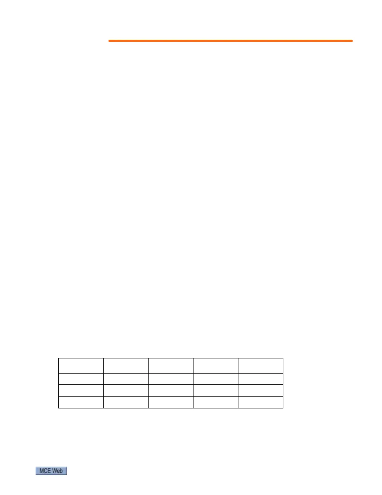
Table 28. Escalator Software Level
PICK HOLD RELEVEL Flash Sets Value
OFFONONFirst3
ON ON ON Second 7
OFF OFF OFF OFF 0