Motion 3000ES Escalator Control
28 Manual # 42-02-E001
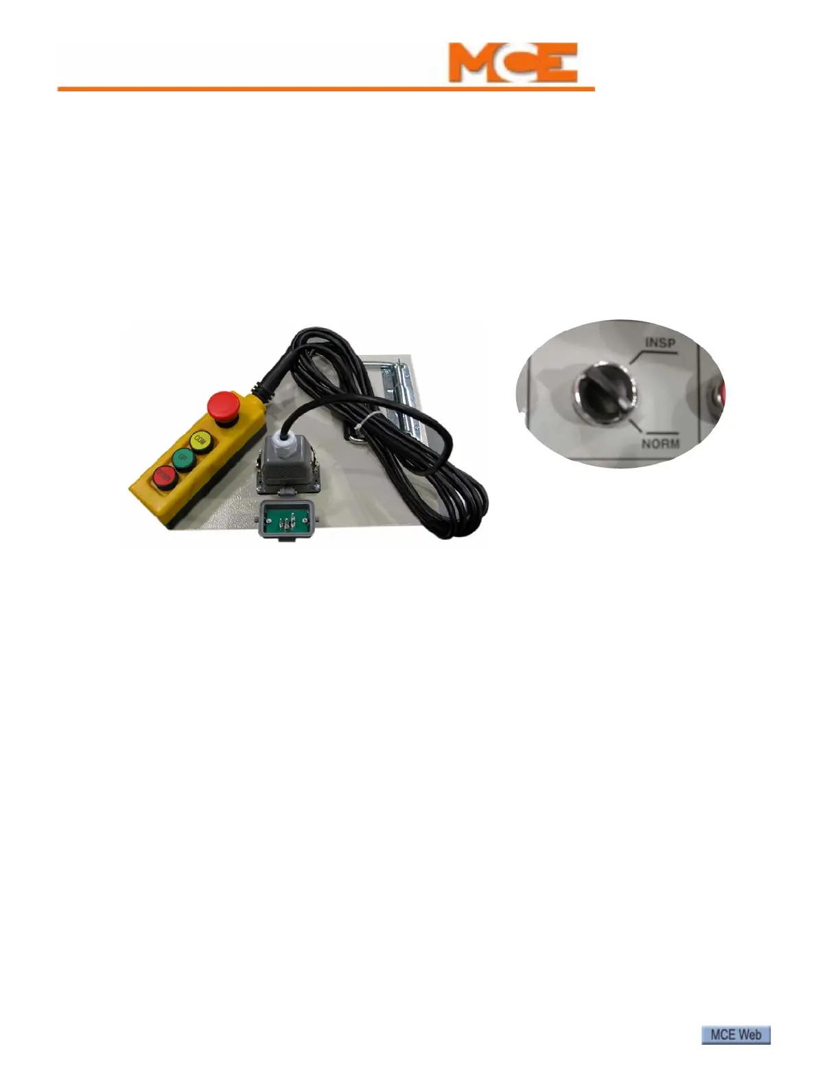
Remote Inspection Control Connection Special sockets for connecting remote
inspection controls are provided. The sockets are covered and, as soon as a socket cover is
opened, the escalator is placed in Inspection mode and stopped. Depending on job require-
ments, these sockets may be mounted on the control enclosure and/or remotely in locations
specified by the customer.
For any inspection socket to be active, the escalator control must be in Normal mode. If two or
more inspection control devices are inadvertently connected at any one time, all inspection
sockets are immediately disabled.
Figure 8. Remote Inspection Socket and Control
Brake Pick and Drop Check that the brakes are picking to running clearance. If avail-
able, check brake labeling or documentation for recommended pick voltage and verify that the
controller is supplying the correct voltage. During initial setup, we recommend setting brake
resistance (RB1 and RB2) to three times the resistance across the brake coils for primary and
auxiliary brakes. If necessary, adjust brake resistance to achieve the desired drop time.
For PM disk brake control, please refer to the job drawings for brake adjustment instructions
and to the mBrake section in this manual for a detailed description.
In order for the remote socket to be
active, the controller Inspection/Nor-
mal switch must be set to NORM.