Motion 3000ES Escalator Control
16 Manual # 42-02-E001
Proximity Sensors / Rail and Step Speed
The proximity sensors used to check rail speed and step speed/presence are listed below. Con-
nect sensors as shown in the job prints. Each sensor has three or four wires (system depen-
dent):
• Brown: 24 VDC
•Blue: Common
•Black: Data
• White (if present): Not Used
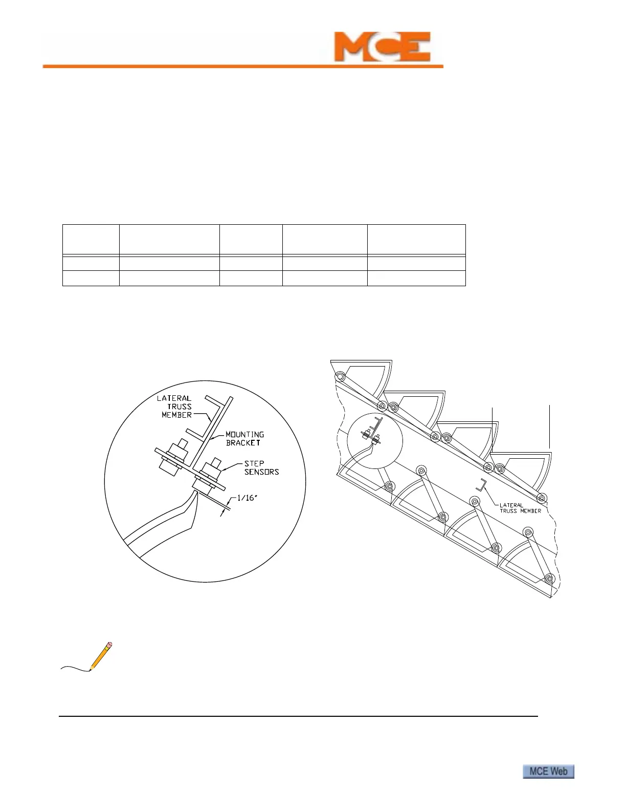
Step Sensors Each processor board (MCB, SCB) has inputs for two step sensors (S1, S2).
MCB sensors are located at the top of the escalator. SCB sensors are located at the bottom of the
escalator. Refer to Tables 2 and 6 for input terminal connections.
Figure 2. Step Sensor Mounting
1. Measure the escalator step tread width (see Figure 2). Step sensors must be spaced less
than a half step width apart.
DO NOT place sensors EXACTLY 1/2 tread width apart because this will prevent the controller
from being able to sense motion reversal or slippage. Please refer to “Sensor Spacing Timing
Diagram” on page 17.
Table 1. Step and Rail Proximity Sensors
Location Output Type
Operation
Range
Recommended
Output Level
Sensor/Target
Clearance
Hand Rail Open Collector, PNP 10 - 40 VDC 18 VDC 4mm (0.15 inches)
Step Open Collector, PNP 10 - 40 VDC 18 VDC 15mm (0.5 inches)