Installation
17
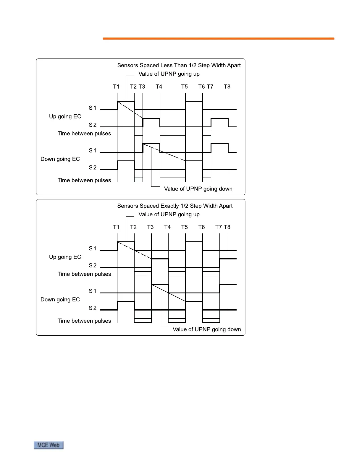
Figure 3. Sensor Spacing Timing Diagram
2. Remove one step.
3. Move the opening to the top of the incline. Position the opening near a lateral truss
member at the top of the incline, just downhill from the curved transition tracks.
4. Assemble the step sensors (PN 33-20-0010) with jam nuts and lock washers to mount-
ing brackets as shown in Figure 2. Hand-tighten the nuts so that the sensors are cen-
tered (equal amount of adjustment thread above and below the bracket flange).
5. Position the sensor bracket against the lateral truss member so that the sensors are
approximately 1/8” from the riser of a return side step (see Figure 2). It may be neces-
sary to jog the escalator so that the return side riser is positioned correctly near the lat-
eral truss member. Mark the lateral cross member at locations where two mounting
holes will be drilled.
When sensors S1 and S2 are
spaced less than 1/2 step
width apart, the time from
leading edge of S1 to lead-
ing edge of S2 is shorter
going up and longer going
down (dotted lines). Time
between sensors is shorter
than time between steps
(blocks).
When sensors S1 and S2 are
spaced exactly 1/2 tread
width apart, the time from
leading edge of S1 to lead-
ing edge of S2 (dotted lines)
is the same going either up
or down. In this case, the
controller will not be able to
sense motion reversal. Time
between sensors (blocks) is
the same as time between
steps.