Motion 3000ES Escalator Control
18 Manual # 42-02-E001
6. Drill mounting holes in the lateral truss member.
7. Install the upper step sensors. Set the running clearance to 1/16” (1.59 mm) max.
Tighten the hardware.
8. Connect cables (PN 33-20-0012) to the sensors. Extend the cables from the sensors to
the top escalator pit. Secure the cables with wire ties, being careful to route the cables
away from moving steps, handrails, chains, etc. Route cables away from high voltage
power and motor leads. Label the ends of the wires “TOP STEP SENSORS”.
9. Slowly jog the escalator to confirm that the steps clear the sensors without interference.
10. Move the opening to the bottom of the incline. Step opening should be positioned near a
lateral truss member at the bottom of the incline, just uphill from the curved transition
tracks.
11. Repeat steps 5 through 7 for the bottom sensors.
12. Connect cables (PN 33-20-0012) to the bottom sensors. Extend the cables from the sen-
sors to the bottom escalator pit. Secure the cables with wire ties, being careful to route
the cables away from moving steps, handrails, chains, etc. Label the ends of the wires
“BOTTOM STEP SENSORS”.
13. Slowly jog the escalator to conform that the steps clear the sensors without interference.
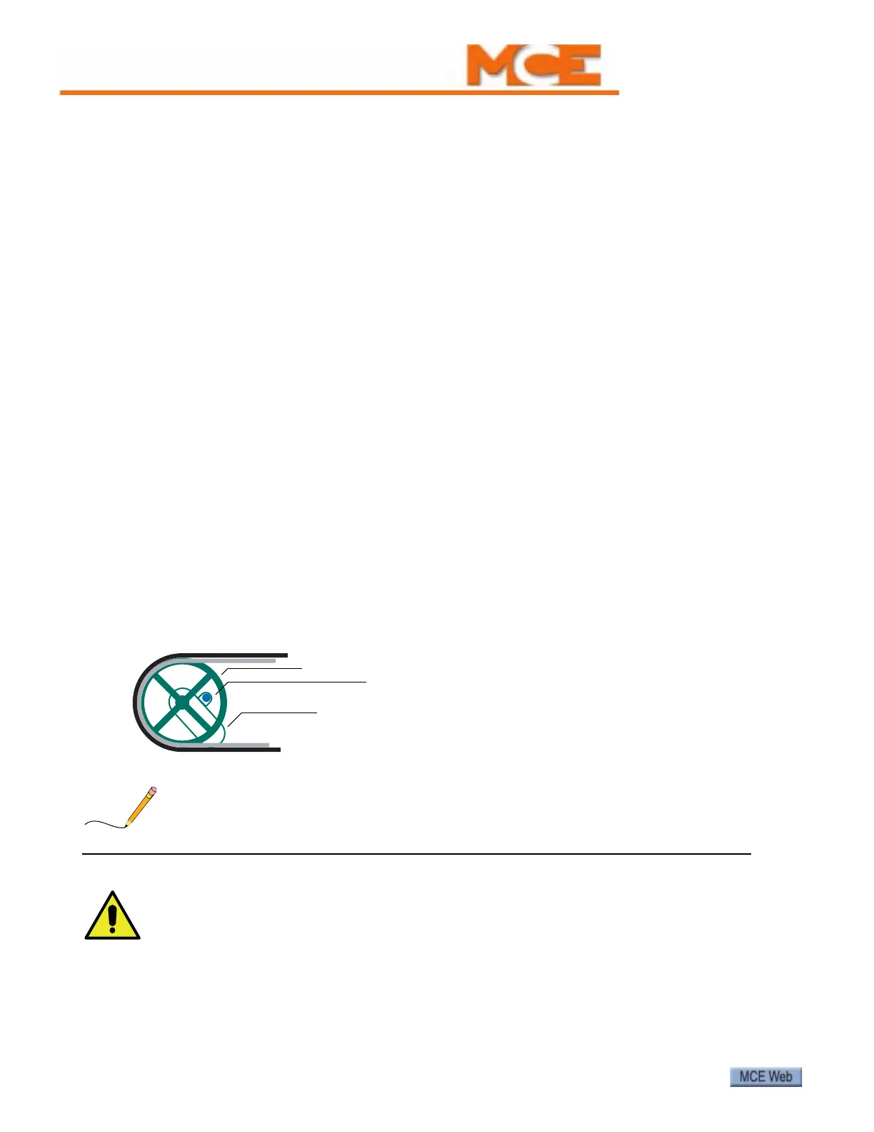
Rail Speed Sensors Each processor board (MCB, SCB) has inputs for two (left and
right) handrail speed sensors. Sensors are mounted on the upper stanchions so that they detect
the passage of the newell wheel spokes. One set of sensors (left and right) are connected in par-
allel to both processor boards. Refer to the job prints. Refer to Tables 2 and 6 for input terminal
connections.
Figure 4. Rail Speed Sensor Locations
Adjust rail sensors so that the face of the sensor is 1/8” (3mm) from the spoke.
All sensors, settings, and learn operations related to step and rail speed must be carefully
completed. Speed related settings and sensors are critical to safe operation of the escalator.
Accurate installation and operating safety are the responsibility of installation and mainte-
nance personnel.
Newell wheel
Rail speed sensor PN 33-20-0011)
Stanchion