Installation
19
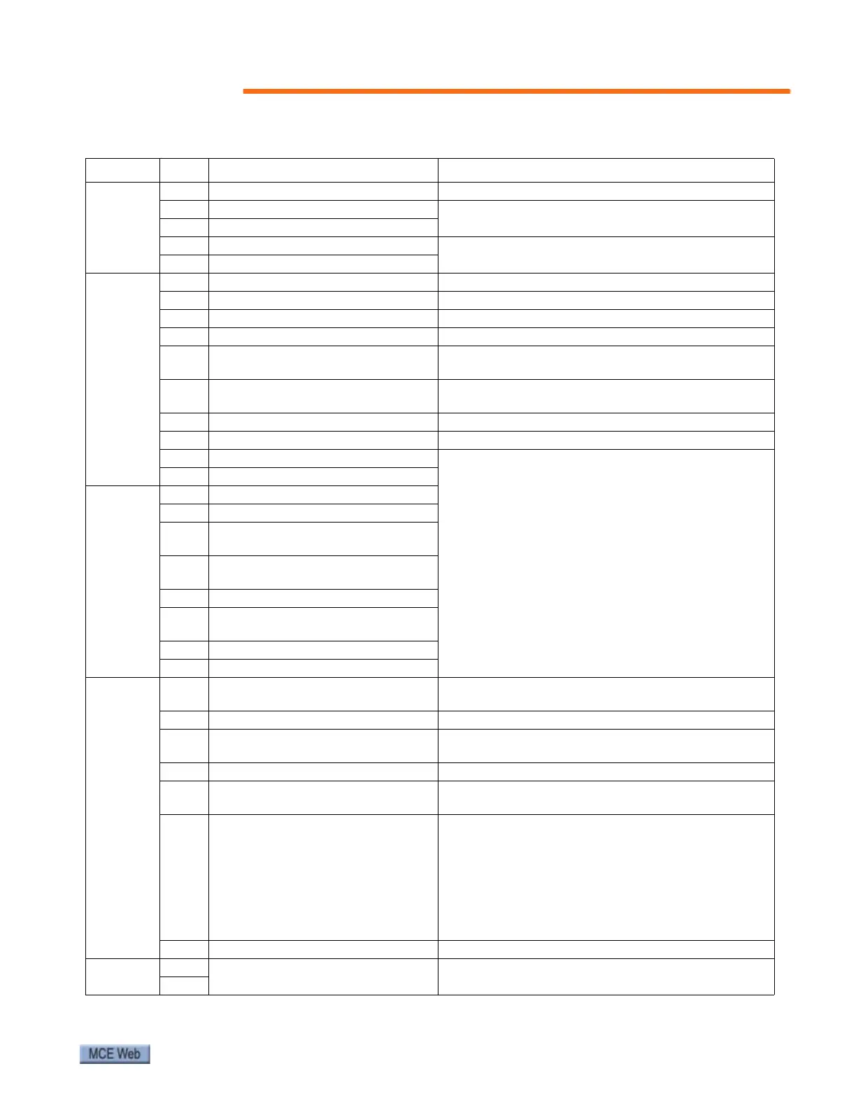
Table 2. EC-MCB Input Connector Descriptions: J1, J2, J3, J4, J5, J6, J11
Terminal No. Function Remark
J1
S1 Spare speed sensor input Not used
S2 Step Sensor #1
S2 and S3 monitor direction, step speed, and miss-
ing steps for Sensors #1 and #2 respectively.
S3 Step Sensor #2
S4 Left handrail speed monitoring
Pulse input. Frequency between 0.5-25HZ
S5 Right handrail speed monitoring
J2
P1 Normal/inspection mode select High = Normal. Low = Inspection.
P2 Normal operation run High = Normal operation, Run selected
P3 Run up High = Run up
P4 Run down High = Run down
P5 Contactor proving input
Open/Low = run disabled
Closed/High = run enabled
P6 Safety circuit
Low = Open safety, run disabled
High = Safety OK, run enabled, LED ON
P7 Manual lubrication Oil pump operation button, High = on
P8 Brake contact input N/O, N/C can be selected through the menu
P9 Programmable: See Note 1.
Active high inputs. Any active input will open the
safety string, stopping the escalator. Under fault
conditions, there will be +24V at these terminals.
Note 1: Some LCD software versions allow pro-
grammable error messages when this input is acti-
vated: Reverse Phase, Speed Governor, Reverse
Phase or Motor Efficiency Controller fault, Motor
Efficiency Controller Fault. Parameter F4-16 is used
to define the error message.
P10 Motor overheat sensor
J3
P11 Upper left skirt obstruction
P12 Upper right skirt obstruction
P13
Upper left comb-step impact detec-
tion
P14
Upper right comb-step impact
detection
P15 Upper left handrail entry detection
P16
Upper right handrail entry detec-
tion
P17 Upper step level detection
P18 Upper step upthrust detection
J4
P19 Broken drive chain detection
Activation of this input will also cause the aux.
brake to drop.
P20 Upper stop switch Controlled stop.
P21 Smoke detector
High = smoke detector active. Stop delay time
adjustable through controller parameter F2-10.
P22 Auxiliary brake contact High = brake lifted, run enabled.
P23 Upper entry detector
Active with VVVF drive when energy saving mode is
selected.
P24 Programmable: See Note 2.
Emergency stop when activated.
Note 2: Some LCD software versions allow pro-
grammable error messages when this input is acti-
vated: Seismic Fault, Tandem Fault, Broken Belt,
Brake Wear, Broken Step Chain, Brake Overheat,
Speed Governor. Parameter F4-17 is used to define
the error message.
CM7 COM Common for S1-P23.
J11
24V+
DC24V power supply Note polarity. Wire correctly.
24V-