Motion 3000ES Escalator Control
20 Manual # 42-02-E001
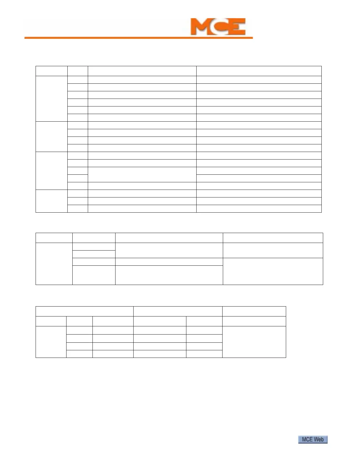
Table 3. EC-MCB Output Connector Descriptions: J7, J8, J9, J10
Terminal No. Wye/Delta drive mode ATL and VVVF drive mode
J7
T1 Wye contactor Power contactor
T2 Delta contactor Running contactor
T3 Brake contactor Brake contactor
CM1 T1 - T3 common T1 - T3 common
T4 Auxiliary brake contactor Auxiliary brake contactor
CM2 T4 common T4 common
J6
T5 Lubrication contactor Lubrication contactor
CM3 T5 common T5 common
T6 Alarm bell Alarm bell
CM4 T6 common T6 common
J8
T7 Up contactor Up contactor/Run up
T8 Down contactor Down contactor/Run down
T9 High speed
T10 Low speed
CM5 T7-T10 common T7-T10 common
J9
T11 Normal running signal output Normal running signal output.
T12 Fault contact, LED ON = No fault Fault contact, LED ON = No fault
CM6 T11-T12 common T11-T12 common
Table 4. EC-MCB J12 Connector Description
Terminal No. Component Remark
J12
TB
RS485 interface for remote monitoring
TA
CL1 Connect with CL1 terminal on EC-SCB Communication between EC-MCB
and EC-SCB; upper entry display
board (if equipped); upper LCD
panel (if equipped)
CH1 Connect with CH1 terminal on EC-SCB
Table 5. EC-MCB J13 Connector Description
Connect from EC-MCB Connect to MC-MPU
Terminal No. Component Terminal No. Remark
EC-MCB
J13
CH 2
CAN
BUS H
HC-MPU J4 CAN H
Remote monitoring
CL 2
CAN
BUS L
HC-MPU J4 CAN L
24V- -24VDC HC-MPU J9 16V2
24V+ +24VDC HC-MPU J9 16V1