Motion 3000ES Escalator Control
68 Manual # 42-02-E001
Bottom Board, TC-FCP
The FCP board transforms AC input power (single or three phase) into the DC output voltage
required to control the brake. The in-line connectors on the board are sized to handle higher
voltage and current.
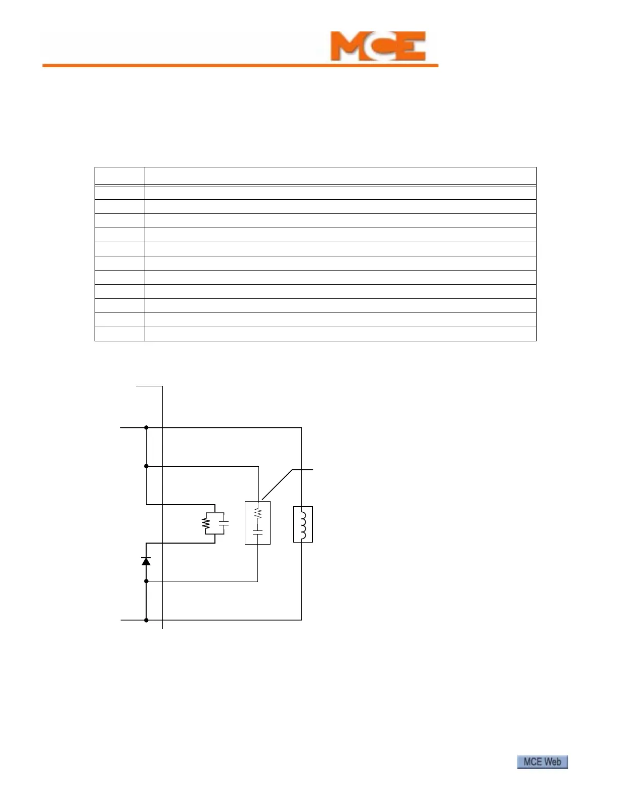
Figure 11. External Filtering
Table 27. In-Line Connectors Pin Assignment
Pin Function
J2, SN1 With SN2, connection point for external filter provided with unit
J2, SN2 With SN1, connection point for external filter provided with unit
J2, SN3 With J3, SN4, connection point for user-provided external filter
J3, SN4 With J2, SN3, connection point for user-provided external filter
J3, FCO- With FCO+, provides power to energize brake coil under normal logic conditions
J3, FCO+ With FCO-, provides power to energize brake coil under normal logic conditions
J5, DT1 Factory Only. Production testing.
J5, DT2 Factory Only. Production testing.
J5, FCL1 AC input, with J6, FCL2 for single-phase use or J6, FCL2/FCL3 for three-phase use
J6, FCL2 AC input, with J5, FCL1 for single-phase use or J5, FCL1/J6 FCL3 for three-phase use
J6, FCL3 AC input, with J5, FCL1 and J6, FCL2 for three-phase use.
Module
FCO+
SN4
SN2
SN1
SN3
FCO-
Filter
Optional
Filter
Brake Coil