Configuration
23
The processor boards, EC-MCB and EC-SCB can each use up to four (optional) display boards.
The last display board in each chain must have an impedance matching resistor to properly ter-
minate the CAN bus. Jumper J1 on the display board (EC-DISP) is used to enable or disable the
impedance matching resistor. The PI boards also have a jumper that determines their position
(top or bottom of escalator).
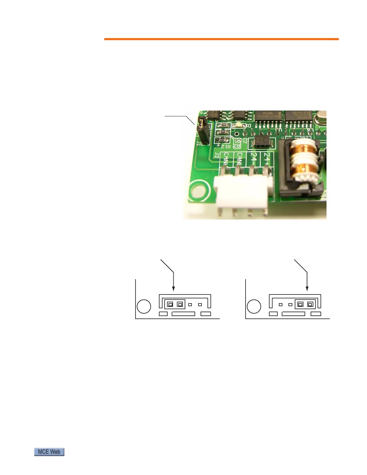
Figure 6. Display Board CAN Termination
Figure 7. Display Board Position Jumper
This jumper, J1, must be in place on the
final display board if multiple display boards
are connected to one of the processor
boards (EC-MCB or EC-SCB). Remove the
jumper on intervening boards.
If only one display board is connected, the
jumper must be in place.
J3
Edge of board
TOP position
J3
Edge of board
BOTTOM position
The position of the jumper on J3
determines whether the PI board
is set for use at the TOP or at the
BOTTOM of the escalator.