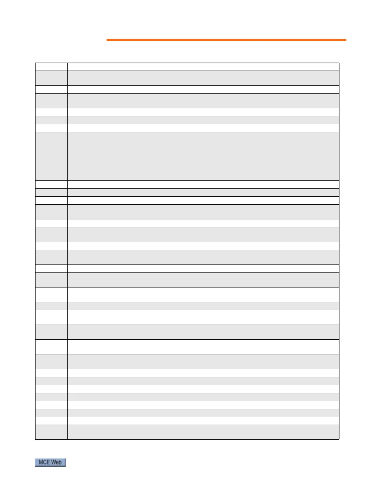
Fault Conditions
59
Ph.P Power module phase loss detection
107
Ensure all three phases are present and balanced
Check input voltage levels are correct (at full load)
PS Internal power supply fault
5
Remove any Solutions Modules and reset Check integrity of interface ribbon cables and connec-
tions (size 4,5,6 only) Hardware fault - return drive to supplier
PS.10V 10V user power supply current greater than 10mA
8 Check wiring to terminal 4 Reduce load on terminal 4
PS.24V 24V internal power supply overload
9
The total user load of the drive and Solutions Modules has exceeded the internal 24V power sup-
ply limit. The user load consists of the drive digital outputs plus the SM-I/O Plus digital outputs,
or the drive main encoder supply plus the SM-Universal Encoder Plus and SM-Encoder Plus
encoder supply.
• Reduce load and reset
• Provide an external 24V >50W power supply
• Remove any Solutions Modules and reset
rS Failure to measure resistance during autotune or when starting in open loop vector mode 0 or 3
33 Check motor power connection continuity
SCL Drive RS485 serial comms loss to remote keypad
30
Refit the cable between the drive and keypad Check cable for damage Replace cable Replace key-
pad
th Motor thermistor trip
24
Check motor temperature Check thermistor continuity Set Pr 7.15 = VOLt and reset the drive to
disable this function
thS Motor thermistor short circuit
25
Check motor thermistor wiring Replace motor thermistor Set Pr 7.15 = VOLt and reset the drive
to disable this function
tunE Autotune stopped before completion
18
The drive has tripped out during the autotune The red stop key has been pressed during the
autotune The secure disable signal (terminal 31) was active during the autotune procedure
tunE1
The position feedback did not change or required speed could not be reached during the inertia
test (see Pr 5.12)
11 Ensure the motor is free to turn i.e. brake was released Check encoder coupling to motor
tunE2
Position feedback direction incorrect or motor could not be stopped during the inertia test (see Pr
5.12)
12
Check motor cable wiring is correct Check feedback device wiring is correct Swap any two motor
phases (closed loop vector only)
tunE3
Drive encoder commutation signals connected incorrectly or measured inertia out of range (see
Pr 5.12)
13
Check motor cable wiring is correct Check feedback device U,V and W commutation signal wiring
is correct
tunE4 Drive encoder U commutation signal fail during an autotune
14 Check feedback device U phase commutation wires continuity Replace encoder
tunE5 Drive encoder V commutation signal fail during an autotune
15 Check feedback device V phase commutation wires continuity Replace encoder
tunE6 Drive encoder W commutation signal fail during an autotune
16 Check feedback device W phase commutation wires continuity Replace encoder
tunE7 Motor number of poles set incorrectly
17
Check lines per revolution for feedback device Check the number of poles in Pr 5.11 is set cor-
rectly
Table 20. CT Drive Fault Displays