2.5 Transmission Specifications
2-13
2.5.9 Connection of D-SUB Connector Pins
The connection of D-SUB connector pins is shown below.
NCP01 board (D-SUB9P)
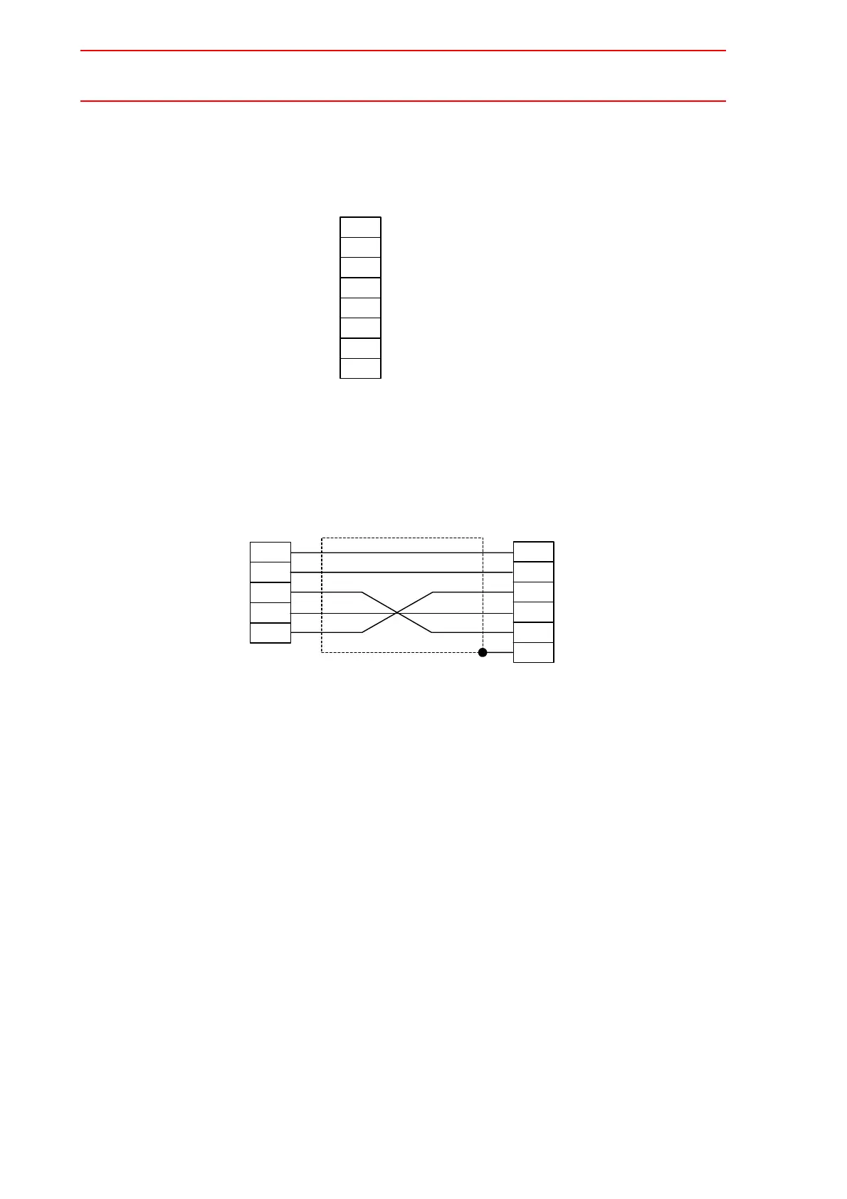
2.5.10 Connection
Since the system is “null-modem”, connect the pins as shown below.
XCP01 board
• Connect “RS” of the NX100 to “CS” of a host computer. This prevents data overrun when
reception processing speed of the NX100 cannot catch up with data sending from the
host computer. In other words, “RS” signal from the NX100 controls start-hold of data
transmission from the host computer. The sending interface controller must be capable of
coping with CS input displacement in units of a single byte.
• The NX100 sends data when the “CS” signal is ON.
1
2
3
4
5
7
8
9
NX100
CD
RD
SD
ER
SG
RS
CS
FG
Carrier detect
Data receive
Data send
Data terminal ready
Grounding for signal
Request to send
Sending enabled
Protective grounding
3
2
7
8
5
Host Computer
SD
RD
RS
CS
SG
2
3
5
7
8
9
NX100
RD
SD
SG
RS
CS
FG
 Loading...