Basic Theory of Operation: Digital (ASTRO) Mode of Operation 3-7
3.3 Digital (ASTRO) Mode of Operation
In the ASTRO (digital) mode of operation, the transmitted or received signal is limited to a discrete
set of frequency deviation levels. The receiver handles an ASTRO-mode signal identically to an
analog-mode signal, up to the point where the DSP decodes the received data. In the ASTRO
receive mode, the DSP uses a different algorithm to recover data.
In the ASTRO transmit mode, microphone audio is processed identically to an analog mode, with the
exception of the algorithm the DSP uses to encode the information. Using this algorithm, transmitter
FM deviation is limited to discrete levels.
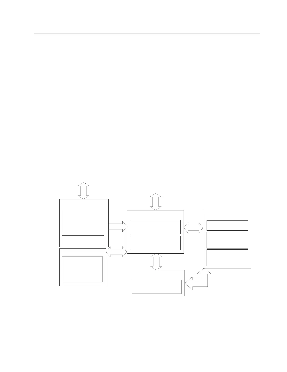
3.4 Controller Section
The controller section (See Figure 3-7.) comprises of five functional sections that are split among two
boards, which are the main and keypad boards. The main functional section consists of a dual core
ARM and DSP controller, Flash memory, and a Double Data Rate Synchronous Dynamic Random
Access Memory (DDR SDRAM) and CPLD for GPIO expander multiple clock generation and SSI
interface for the radio system. The Power and Clocks section includes a power management IC
(MAKO) and various external switching regulators, and three clock sources (12 MHz and 24.576
MHz) from which all other controller digital clocks are derived. The Audio section has a CODEC and
a class-D audio power amplifier that provides the radio with a microphone and speaker design. The
User Interface section provides communication and control to the main Liquid Crystal Displays
(LCD) on the radio, as well as a keypad and a side connector interface conforming to GCAI (Global
Communications Accessory Interface) specifications.
Figure 3-7. Controller Block Diagram
Battery Supply
POWER & CLOCKS
Voltage Regulators
USER INTERFACE
AUDIO
Data Microphone
Audio PA/ Speaker
Main Microphone
Acc. Speaker
Acc. Microphone
Clock sources:
12MHz,
24.576Mhz,
32.768kHz
Main Display
Keypad
Side connector
Top Controller
Flash Memory
DDR Memory
ARM Processor
Digital Signal Processor
CONTROLLERS & MEMORY
Transceiver
Keypad Board (Full version)
GPS (On Main Board)
GPS

 Loading...