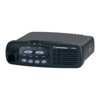
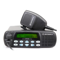
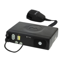
Dash Mounting 17
Do not short pin 16 on the accessory connector to ground, as this may damage the radio.
Connection Plan for Emergency Switch
Figure 16 Connection Plan for Emergency Switch
• Remove the jumper wire from locations 4 and 9 in the accessory plug.
• If installed, remove the jumper wire from locations 1 and 2.
Connection Plan and Installation of Ignition Sense Cable
Figure 17 Connection Plan for Ignition Sense Cable
• Remove the jumper wire from locations 4 and 9 in the accessory plug.
• If installed, remove the jumper wire from locations 1 and 2.
• Connect the jumper wire to locations 21 and 10. (If an external emergency switch is
installed, do not connect a jumper wire to locations 21 and 10—see above.)
!
C a u t i o n
VIEW UPON
INSERTION SIDE
ACCESSORY
CONNECTOR
13
1
2514
21
EMERGENCY
SWITCH
15
VIEW UPON
INSERTION SIDE
ACCESSORY
CONNECTOR
13
1
2514
IGNITION
SENSE
CABLE
SWITCHED BATTERY VOLTAGE

 Loading...


