CA Series User’s Manual Hardware Installation
2-5
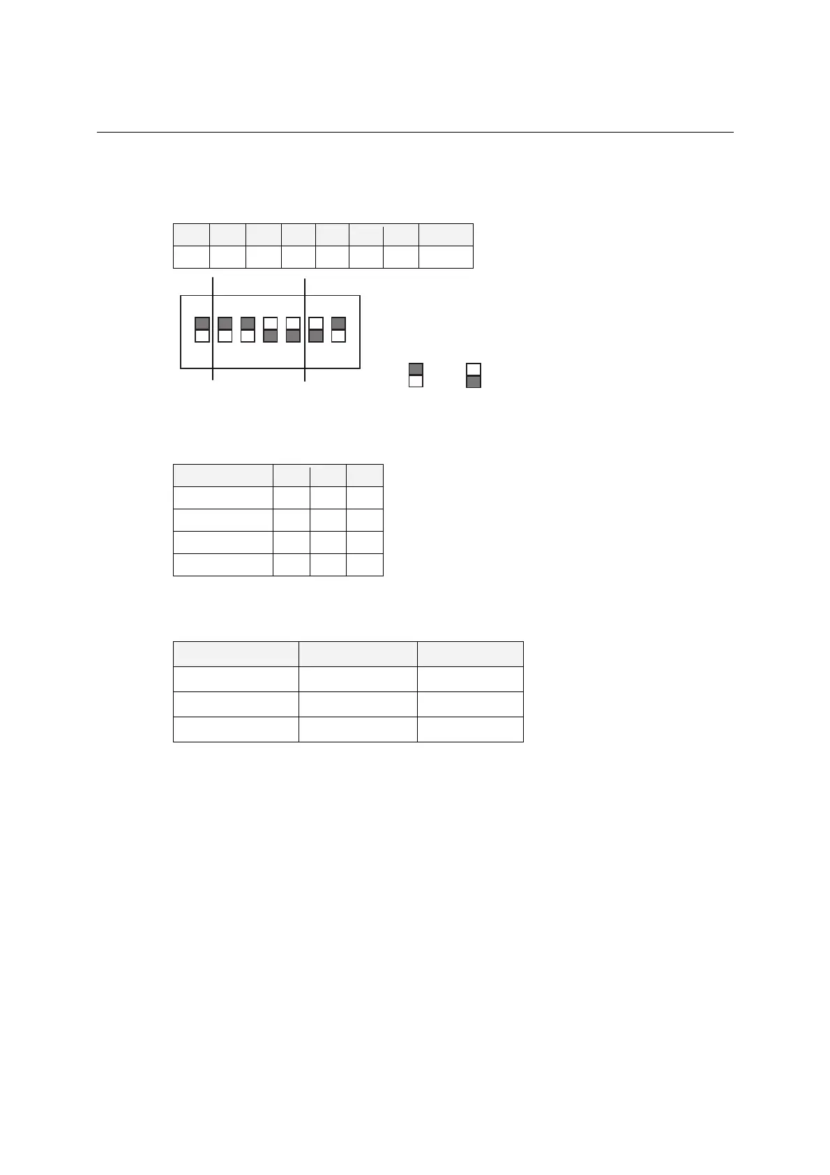
Interrupt Vector
Use DIP switch SW2 to set port 1’s interrupt vector. The default interrupt vector is 0×1C0, with
SW2 set as follows:
A3 A4 A5 A6 A7 A8 A9 Hex
ON ON ON off off off ON 0×1C0
ON
DIP
1 2 34567
5
7
01C
= on, = off
Serial Interface
For the CA-114, use S3, S4, and S5 to select the serial interface as follows:
Mode S3 S4 S5
RS-232 --- --- ON
RS-422 --- ON off
4-wire RS-485 ON off off
2-wire RS-485 off off off
For the CA-134I, CA-132 V2, and CA-132I V2, use the 2-WIRE/4-WIRE and RS-422/RS-485
DIP switches to select the serial interface as follows:
Interface 2-WIRE/4-WIRE RS422/RS485
RS-422 --- OFF
4-wire RS-485 OFF ON
2-wire RS-485 ON ON
IRQ
Before selecting an IRQ, please enter the PC’s BIOS and reserve a dedicated IRQ for the module.
On the module, the IRQ is set by a jumper. Before inserting the module into the PC/104 slot, use
the jumper to select an IRQ (3, 4, 5, 6, 7, 9, 10, 11, 12, or 15).