CA Series User’s Manual Hardware Installation
2-2
Hardware Installation
Installing the CA Series module is easy. Before inserting the module into the PC/104 slot, you
must first configure the I/O base address, interrupt vector, IRQ, and serial interface (for select
models).
ATTENTION
Safety First!
To prevent damage to your system or board, make sure your embedded PC’s power is turned off
before installing your CA Series module.
Step 1: Shut off power to your embedded PC and to any peripheral devices. After shutting off
power, remove the cover of your embedded PC.
Step 2: Use the DIP switches on the module to select I/O base address, interrupt vector, IRQ, and
serial interface (for select models). Details for each model are provided later in this
chapter.
Step 3: Insert the module firmly into the embedded PC’s PC/104 slot.
Step 4: Screw the control board in place.
Step 5: Connect the cables.
Step 6: Power on the embedded PC.
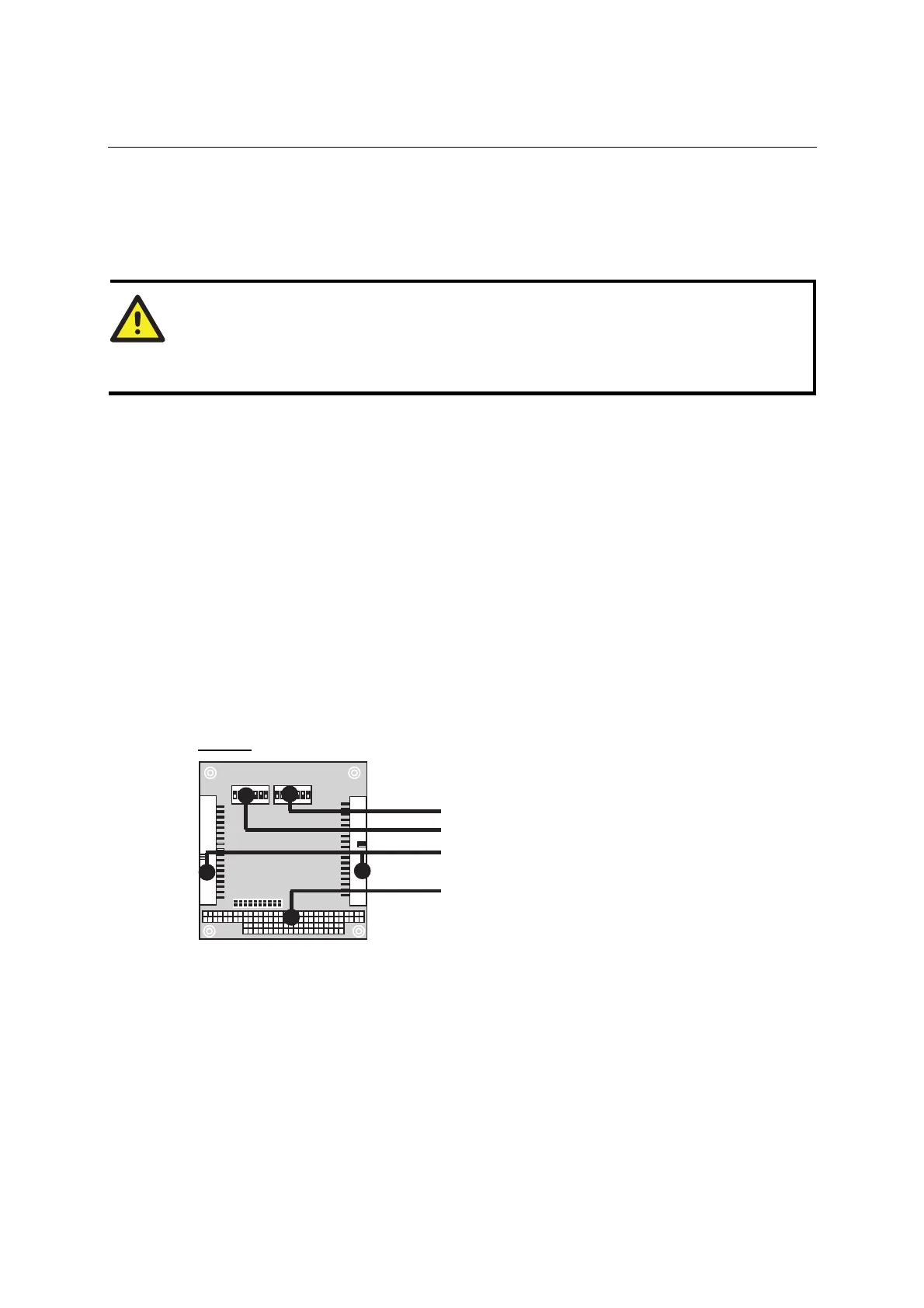
Block Diagrams
CA-108
SW2: Interrupt Vector
SW1: I/O Base Address
Box Header Connector
PC/104 Slot