5
5
Chapter 5Pin Assignments
The box header connector(s) on the module is used to connect to serial devices. Optional cables
are available that provide DB9 or DB25 connectors. The pin assignments of the box header
connectors and available cables are provided below.
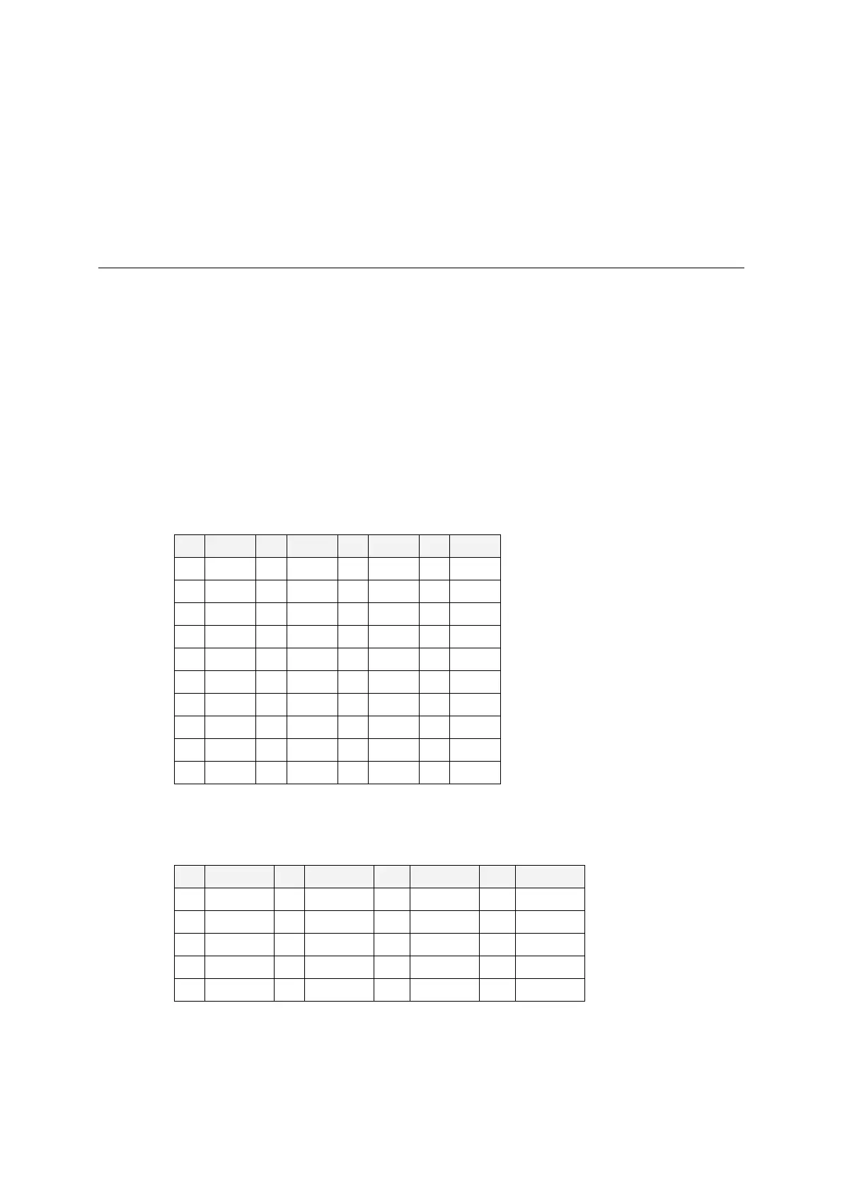
Box Header Pin Assignments
RS-232
These pin assignments apply to the CA-108, CA-114, and CA-104 V2. Note that there are two
40-pin box header connectors on the CA-108, each of which connects to 4 serial ports.
Pin Signal Pin Signal Pin Signal Pin Signal
1 DCD0 11 DCD1 21 DCD2 31 DCD3
2 DSR0 12 DSR1 22 DSR2 32 DSR3
3 RxD0 13 RxD1 23 RxD2 33 RxD3
4 RTS0 14 RTS1 24 RTS2 34 RTS3
5 TxD0 15 TxD1 25 TxD2 35 TxD3
6 CTS0 16 CTS1 26 CTS2 36 CTS3
7 DTR0 17 DTR1 27 DTR2 37 DTR3
8 --- 18 --- 28 --- 38 ---
9 GND0 19 GND1 29 GND2 39 GND3
10 --- 20 --- 30 --- 40 ---
RS-422, 4-wire RS-485
These pin assignments apply to the CA-132 V2, CA-132I V2, CA-114, and CA-134I. Pins 21 to
40 apply to the CA-114 and CA-134I only.
Pin Signal Pin Signal Pin* Signal* Pin* Signal*
1 TxD0-(A) 11 TxD1-(A) 21 TxD2-(A) 31 TxD3-(A)
3 TxD0+(B) 13 TxD1+(B) 23 TxD2+(B) 33 TxD3+(B)
5 RxD0+(B) 15 RxD1+(B) 25 RxD2+(B) 35 RxD3+(B)
7 RxD0-(A) 17 RxD1-(A) 27 RxD2-(A) 37 RxD3-(A)
9 GND0 19 GND1 29 GND2 39 GND3