ioLogik E1200 Series Using the Web Console
support the counter trap function.
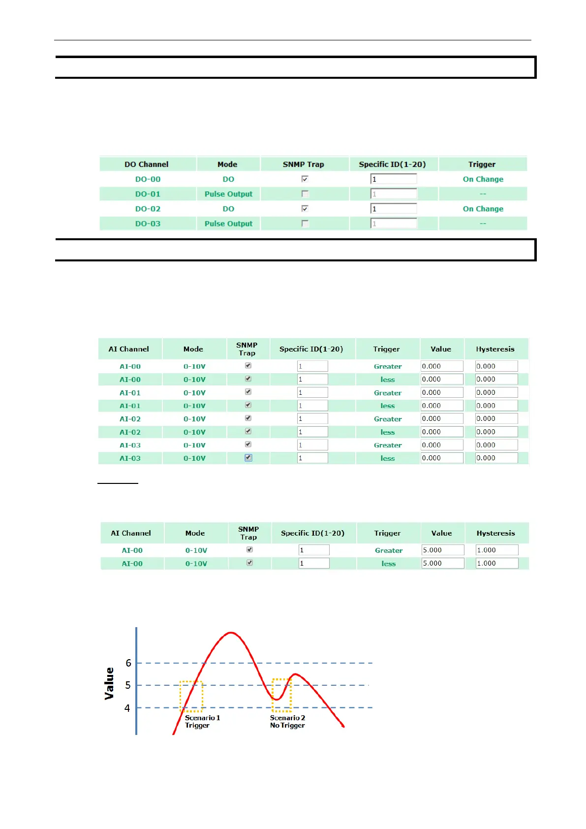
Digital Output/Pulse Output Trap Settings
For digital output, the trap is triggered by the On Change function. When there is a change in the DO channel,
the SNMP will send a trap to the SNMP Server.
support the Pulse Output trap function.
Analog Input Trap Settings
For Analog Input, the trap is triggered when an analog input meets the preset conditions for Trigger, Value, and
Hysteresis. Refer to the AI Channel settings in Chapter 3 to set the mode.
Example:
For illustration purposes, consider the following example where we set the AI-00 channel’s trigger value to be
greater than 5 with a Hysteresis of 1 and also smaller than 5 with a Hysteresis of 1.
When Trigger = Greater, Value = 5, and Hysteresis = 1, the SNMP trap will only be triggered if the analog signal
fluctuates from 4 to 5, as depicted in Scenario 1 below. However, if we change the settings to Value = 5 and
Hysteresis = 2, the SNMP trap will only be triggered if the analog signal fluctuates from 3 to 5.
 Loading...