9 Operation
Maschinenfabrik Reinhausen GmbH 2021100 7817454/02 ENTAPCON
®
230 Expert
If you use this circuit, set the device as follows:
Parameter Option
Voltage-transformer circuit 3Ph differential voltage
Current-transformer circuit 3 Ph phase current
Phase angle correction 30°
Table34: Circuit 1-E
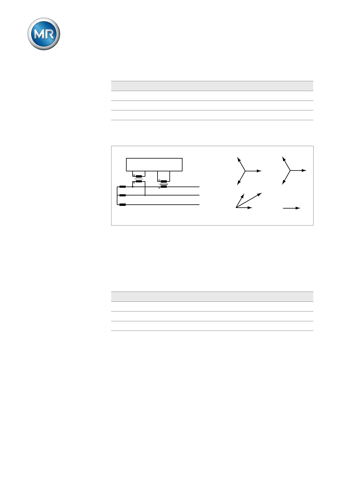
Circuit 1-F
IL1
L1
L2
L3
VT
CT
UL1
IL1
IL2
IL3
UL3
UL2
UL1
UL1-UL2
-UL2
UI
L
N
k
l
▪ The voltage transformer VT is connected to the phase conductors L1 and
L2.
▪ The current transformer CT is looped into the phase conductor L1.
▪ The current I
L1
lags behind voltage U
L1
-U
L2
by 30°. This corresponds to a
phase shift of +30° and a correction value of -30°.
▪ The voltage drop on a phase conductor is determined by the current I
L1
.
If you use this circuit, set the device as follows:
Parameter Option
Voltage-transformer circuit 3Ph differential voltage
Current-transformer circuit 3 Ph phase current
Phase angle correction -30°
Table35: Circuit 1-F
9.2.2 Voltage monitoring
In order to monitor the transformer's current output voltage, you can set
4limit values:
▪ Undervoltage U<<: Lower limit2
▪ Undervoltage U<: Lower limit1
▪ Overvoltage U>: Upper limit1
▪ Overvoltage U>>: Upper limit2

 Loading...