6 Mounting
Maschinenfabrik Reinhausen GmbH 2021 537817454/02 EN TAPCON
®
230 Expert
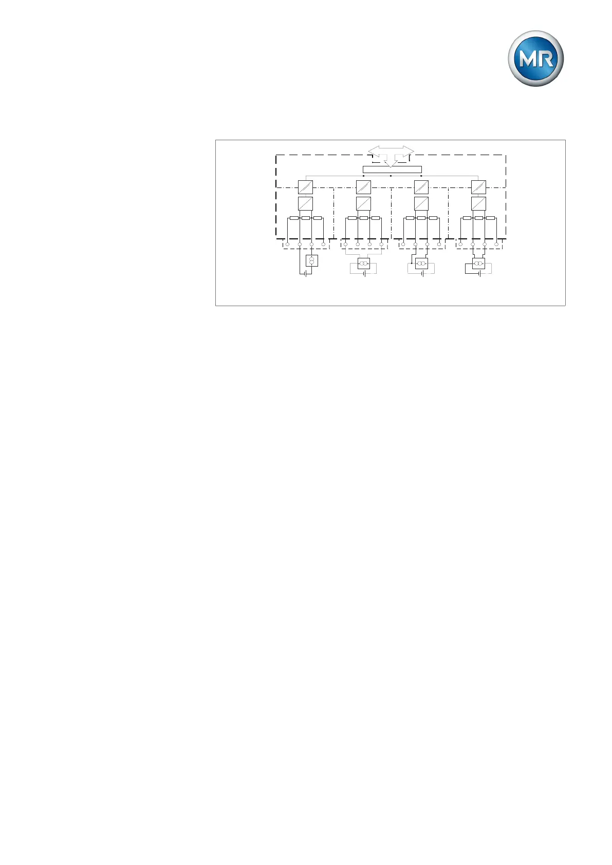
Block diagram and wiring versions
1
X1
IN VO U+
1
2
3
4
IN VO I+
A
D
IN VO I-
IN VO U-
X
2
IN V1 U+
2
3
4
IN V1 I+
A
D
IN V1 I-
IN V1 U-
X3
I
N
V2 U+
1
2
3
4
IN V2 I+
A
D
IN V2 I-
IN V2 U-
X4
IN V3 U+
1
2
3
4
IN V3 I+
A
D
IN V3
I-
IN V3 U-
Connection of a 2-
conductor measuring
transducer with current
output
Connection of a 4-
conductor measuring
transducer with voltage
output
Connection of a 3-
conductor measuring
transducer with current
output
Connection of a 4-
conductor measuring
transducer with current
output
CAN bus
Controller
Reinforced insulation
AI4
Figure38: Block diagram for analog inputs
1. Lead the wires into the connector and fasten them using a screwdriver.
2. Insert the plug into the respective slot in accordance with the connection
diagram [►Section 13.14, Page 160] and screw into place.
6.4.8 Wiring digital inputs DI
If you use digital inputs, these have to be supplied with an auxiliary voltage
of 110VDC.
1. Feed the wires into the terminal of the DI16-110V plug in accordance with
the connection diagram and fasten them using a screwdriver.
2. Plug the connector into the respective slot and screw it into place.
Auxiliary power supply for digital inputs
1. Feed the wires into the terminals X8:2 and X8:1 of the X8 plug in accor-
dance with the connection diagram and fasten them using a screwdriver.
2. Plug the connector into the respective slot and screw it into place.