6. Locate the span gas cylinder and Calibration Kit Flow Controller.
7. Screw the Flow Controller onto the top of the span gas cylinder.
8. Locate the Calibration Kit Tube Assembly.
9. Push the smaller end of the Tube Assembly over the gas outlet of
the Flow Controller and ensure that the tubing completely covers
the gas outlet.
10.When using:
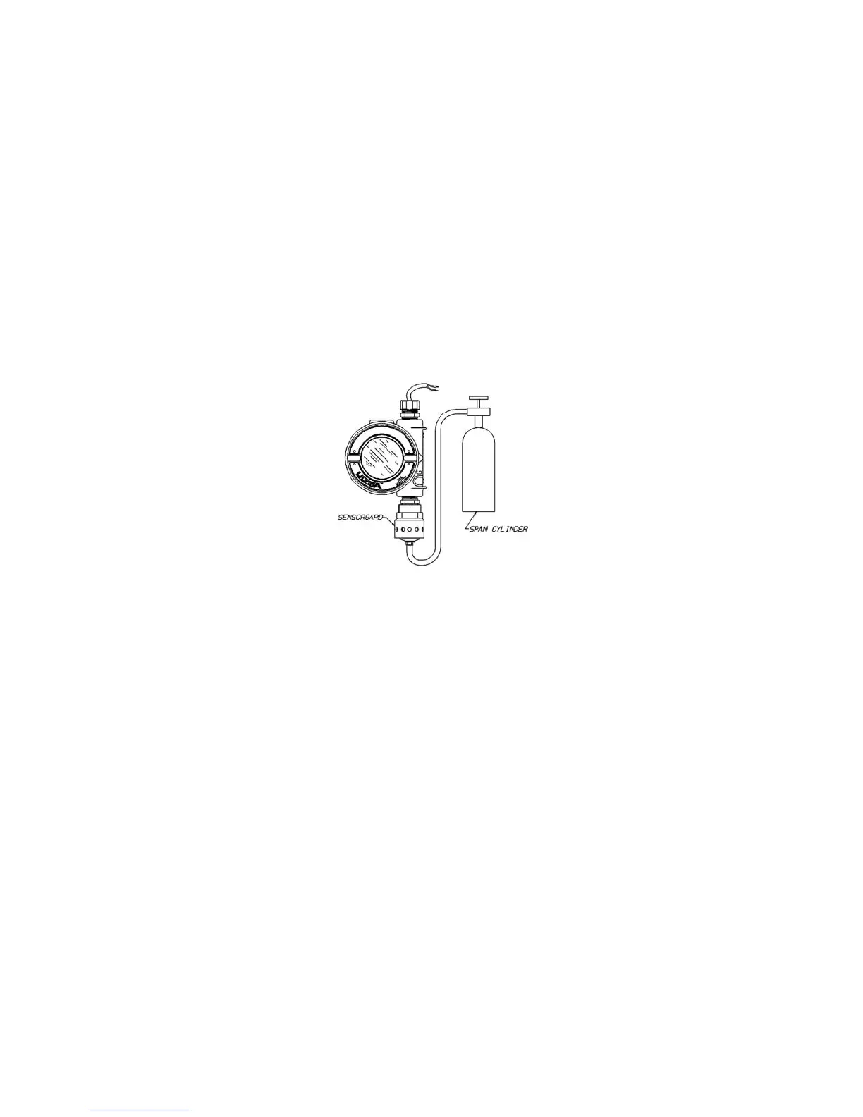
a. Cal Kit 40: connect the other end of the tubing over the
SensorGard inlet (FIGURE 2-6).
b. Cal Kit 41 (or Cal Kit 40 with the Ultima XIR): locate the cal
cap with hole for tubing and push the tubing through the hole
in the bottom of the cap. Then, connect the end of the tubing
over the sensor inlet and push the calibration cap over the
entire sensor inlet (see FIGURE 2-8).
c. Cal Kit 54: Run HCL gas through the regulator and tubing for
five minutes before attempting a calibration.
11. Turn ON the gas flow by turning the flow controller knob.
• It is good practice to have all calibration components
previously assembled.
• Ensure that any calibration gases are applied during the
30-second countdown period.
• If CAL FAULT displays on the Ultima/Ultima X Series Gas
Monitor before the user is able to apply the gas, a stable gas
condition was reached, causing the unit to use a wrong
reading as a span indication.
• It is necessary to restart the calibration process to clear
this condition.
Figure 2-6. Span Set-up (Ultima unit shown)
2-14