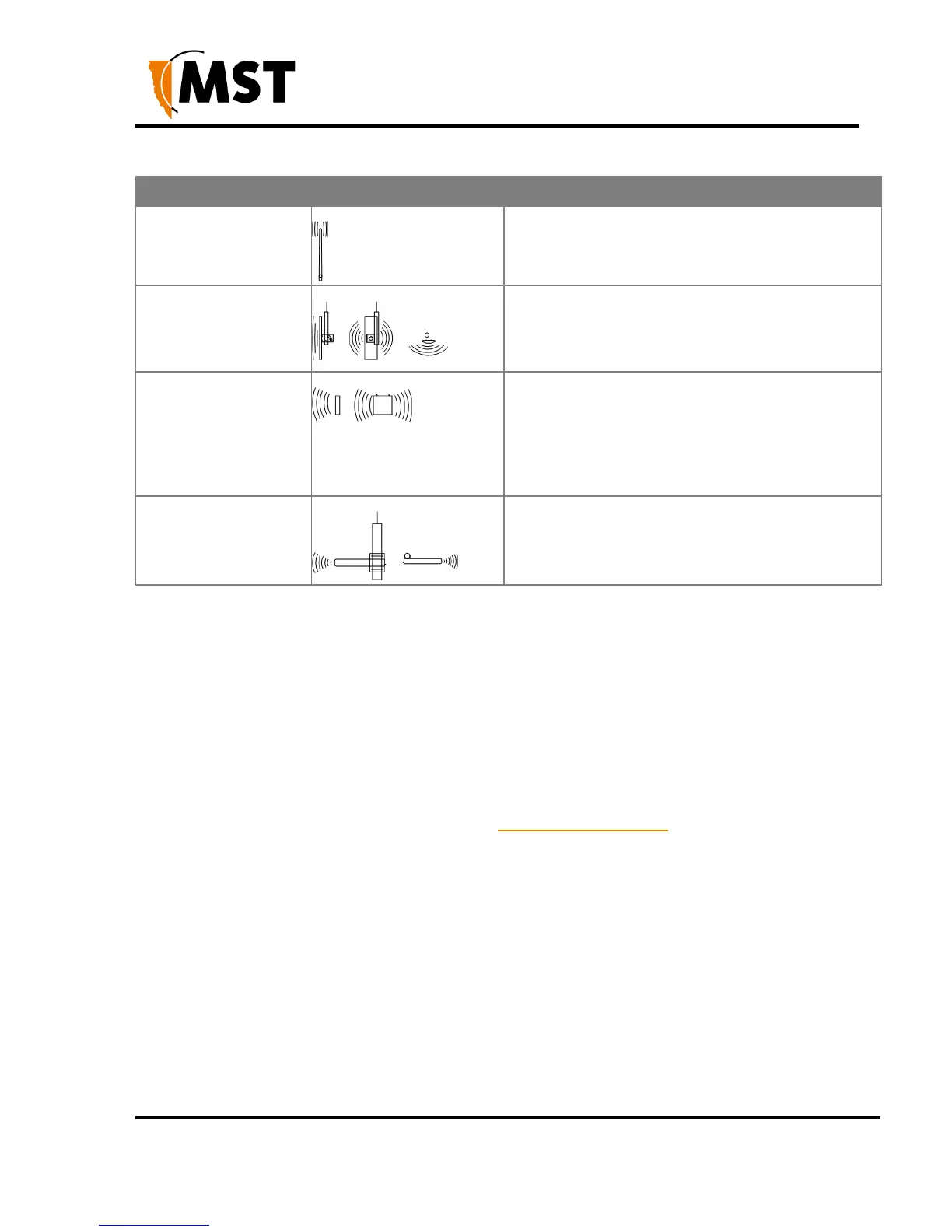
A panel antenna is a directional antenna, with a wide
horizontal beamwidth and narrower vertical
beamwidth. They are suited for covering an open area
in one direction.
A diversity panel antenna contains two panel antennas
in one housing with a 90° rotation between them. It
is used for providing better signal reception in difficult
areas, and more accurate AeroScout tag location when
Wi-Fi tracking is implemented. Diversity antennas
use both antenna connections on a WAC.
A Yagi antenna is high gain directional antenna. They
are ideally suited for line of sight tunnel
communications. Yagi antennas need to be aimed
accurately and avoid obstacles in their RF beam path.
2.4 Placement of NS50 Units
A site inspection will determine the best positioning of cables, NS50 units and antennas prior to
installation. NS50 units with antennas directly attached should be mounted in an elevated position,
within line-of-sight of mobile devices. Ideally this would be situated high up on a tunnel ceiling or on the
rock wall face. The mounting location should be free from debris, and avoid obstruction to vehicles,
equipment/machinery, vent tubing and cables.
NS50 units should not be installed in cut-out areas such as safety bays and remuck bays, due to
signal confinement. In such instances, a WAP is more suitable, connected to the nearest NS50. For
details on common NS50 mounting scenarios, see NS50 Mounting Options on page 15.
2.5 Placement of Antennas
Antennas are usually mounted separately from each NS50 to optimise transmission and avoid any
obstructions in a tunnel. They are connected by coaxial cable. The coaxial connection should be kept
as short as possible to minimise signal attenuation. Larger antennas / longer cable feeds can require
line amplifiers, and possibly bi-directional splitter / combiners for dual antenna systems.
Antenna placement is dependent on the surrounding geology, tunnel topology and stratum type. The
recommended placement of antennas is as follows:
Tip 1: Directionality
Antennas should be mounted and angled to give optimum transmission along curves and dips as
shown below in Figure 5: Angling antennas.
 Loading...