Additional accessories:
• Printer (part no. J-38699) for direct connection to the DDR
• Spare paper (part no. J-38480-5) for the printer (5 rolls respectively)
The following information is available on reading out the fault codes with the DDR.
Example:
33 MID:128 Engine
TURBO BOOST SENSOR
INPUT VOLTAGE HIGH
▴ A1 PID: 102 FMI:3 ▾
Explanation:
• 33 → Flashing code
• MID: 128 →Information about the source of the fault message
• TURBO-BOOST-SENSOR-INPUT-VOLTAGE-HIGH → Fault text
• ▴ ▾ → more faults pending A= active, I= inactive
MID (Message Identification Character)
• Information about the source of the fault message:
MID 128 → Master
MID 175 → Receiver 1
MID 183 → Receiver 2
PID (Parameter Identification Character).
• Information to identify transmitted data: (e.g. engine speed, coolant temperature etc.)
PID 0-127 → 1 data byte
PID 128-191 → 2 data bytes
PID 192-253 → Variable
SID (Subsystem Identification Character)
• Information about the source of fault messages from subordinate systems which may be replaced as a
unit (e.g. injectors).
FMI (Failure Mode Identifier)
• Information about the type of fault which has occurred.
FMI 0 → Measured value above limit value (monitoring of TOO HIGH) example: Coolant temperature
FMI 1 → Measured value below limit value (monitoring of TOO LOW) example: Lube oil pressure
FMI 3 → Signal disrupted or signal above admissible measuring range (sensor failure)
FMI 4 → Signal short-circuited to (-) supply of sensor or signal below admissible measuring range
(sensor failure)
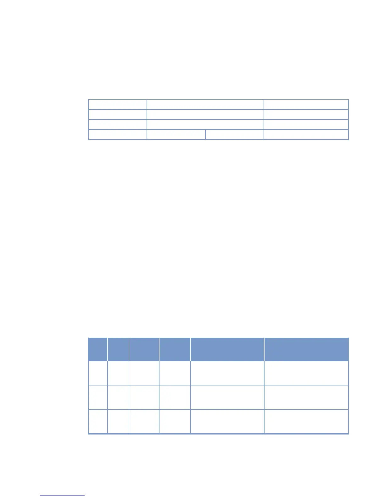
Flashi
ng
code
PID SID FMI Description Maintenance tasks
11 187 4 Position sensor of variable
speed governor → voltage
too low.
Contact Service.
11 187 7 Control system/ variable
speed governor→ voltage
too high.
Contact Service.
12 187 3 Position sensor of variable
speed governor → voltage
too high.
Contact Service.
MS150049/02E 2012-11 | Troubleshooting | 53
TIM-ID: 0000003162 - 002