PAGE 34 — GENERATOR SERVICE AND TROUBLESHOOTING MANUAL — REV. #0 (08/29/23)
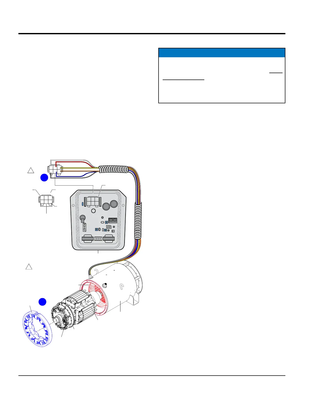
OPEN-DELTA LEAD WIRES
The main armature has four open-delta lead wires.
All wires are black. These wires are designated as
A, B, C and D (Figure 34A). The purpose of these wires is
to supply the supplementary voltage needed to maintain
a steady-state excitation output during the different levels
of load. These four wires are connected to the AVR via the
6-pin plug to the CN1 receptacle.
EXCITATION LEAD WIRES
The stationary exciter eld (Figure 34B) has two black
excitation lead wires and are designated as J and K.
These two excitation lead wires are connected to the AVR
via the 6-pin plug to the CN1 receptacle (Figure 34A).
Figure 34. Open Delta/Excitation Lead Wires
ROTATING
MAIN FIELD
2
C J A
BKD
1
3
YELLOW
WHITE
ORANGE
GRAY
BLUE
RED
AVR
2
C J A
BKD
1
3
PIN NO.
WIRE
LABEL
2
1
A J C
DKB
3
CN1
CN2
CN3
CN4
RECEPTACLE
REAR VIEW
WIRE SIDE
5 4
6
B
1
1
NOTE:
WIRE COLOR SHOWN IS FOR
A DCA-25SSIU4F GENERATOR.
ALL OTHER DCA GENERATORS
USE BLACK WIRES.
6-PIN
PLUG
6-PIN
PLUG
STATIONARY
EXCITER
FIELD
EXCITER
ARMATURE
ROTATING
RECTIFIER
MAIN
ARMATURE
WINDINGS
ENCLOSURE
A
MAIN ARMATURE RESISTANCE TEST
The main armature has 12 load lead wires (Figure 35A)
for DCA150 model generators and below. DCA180
model generators and above have 10 load lead wires
(Figure 35B). All wires are black.
The 12 load lead wires for DCA150 model generators and
below are designated as U1, X1, U2, X2, V1, Y1, V2, Y2,
W1, Z1, W2 and Z2. These wires are AC outputs and are
connected to the voltage selector switch and main circuit
breaker via the current transformers.
The 10 load lead wires for DCA180 model generators and
above are designated as U1, X, V1, Y, W1, Z, U2, V2, W2
and 0. These wires are AC outputs and are connected to
the voltage change-over board and main circuit breaker
via the current transformers.
Using a multimeter (Figure 35), check the resistance across
each pair of wires as referenced in Table 6, column A.
Be sure to place the selection dial on the multimeter in the
Ω position.
NOTICE
Before performing the main armature windings
resistance test, the load lead wires (Figure 35) must
be disconnected from either the voltage selector
switch or the voltage change-over board. If the reading
indicates an open circuit the component may have to
be replaced or repaired.
MAIN ARMATURE WINDINGS RESISTANCE TEST