PAGE 10 — GENERATOR SERVICE AND TROUBLESHOOTING MANUAL — REV. #0 (08/29/23)
GENERATOR THEORY
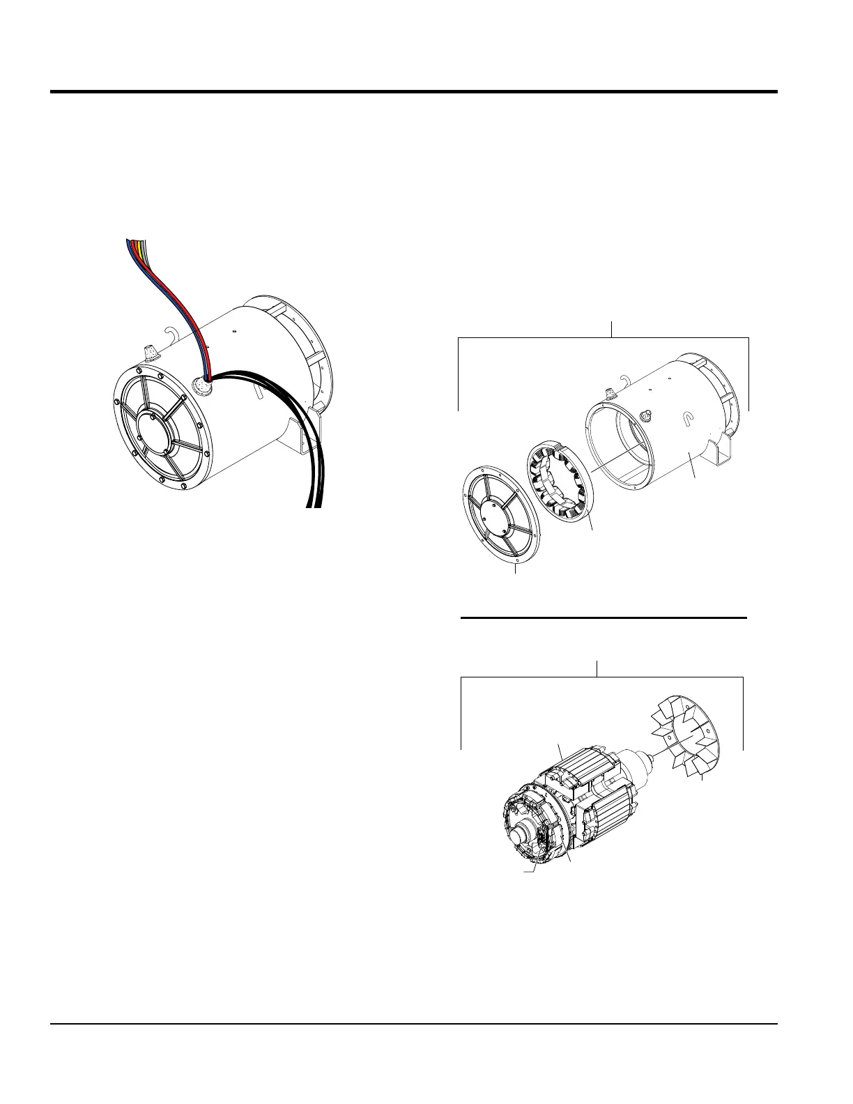
ALTERNATOR
The generator (Figure 1) creates electricity by a series
of ne wire windings inside a magnetic eld, called an
armature. As the rotor rotates inside the magnetic eld
by the diesel engine, current and voltage is generated in
those windings of wire and electricity is transferred.
Figure 1. Typical Alternator
The current and voltage will be directly proportional to
the speed that the rotor rotates and to the strength of the
magnetic eld. Each complete revolution, one complete
cycle of alternating current (AC) is developed. This is called
a rotating rotor.
Most current generator designs, including Multiquip's utilize
a rotating eld type alternator. The magnetic eld rotates
inside the main stator.
The frequency of the generated voltage is dependent on the
number of eld poles that makeup the rotor and the speed
at which the generator is operated. Frequency, measured
in hertz (Hz), is the number of complete cycles per second
in alternating current.
As current ows through the armature, there is some amount
of resistance and inductive reactance. The combination of
these make up what is known as the internal resistance.
When a direct current (DC) voltage is applied to the
stationary exciter eld windings, current ows through the
windings and sets up a steady magnetic eld. This is called
eld excitation.
An exciter is part of the generator package supplying direct
current to the alternator eld windings to magnetize the
rotating poles. The exciter output may be controlled by
a voltage regulator. A regulator is an important option to
consider if there is frequency or voltage sensitive equipment
such as computers.
ALTERNATOR COMPONENTS
The alternator is broken down into two major components
Stator Assembly and Rotor Assembly.
Figure 2. Stator and Rotor Assemblies
ROTATING
MAIN
FIELD
EXCITER
ARMATURE
FAN
ROTATING
RECTIFIER
ROTOR ASSEMBLY
STATIONARY
EXCITER
FIELD
MAIN
ARMATURE
STATOR ASSEMBLY
END
BRACKET