GENERATOR SERVICE AND TROUBLESHOOTING MANUAL — REV. #0 (08/29/23) — PAGE 47
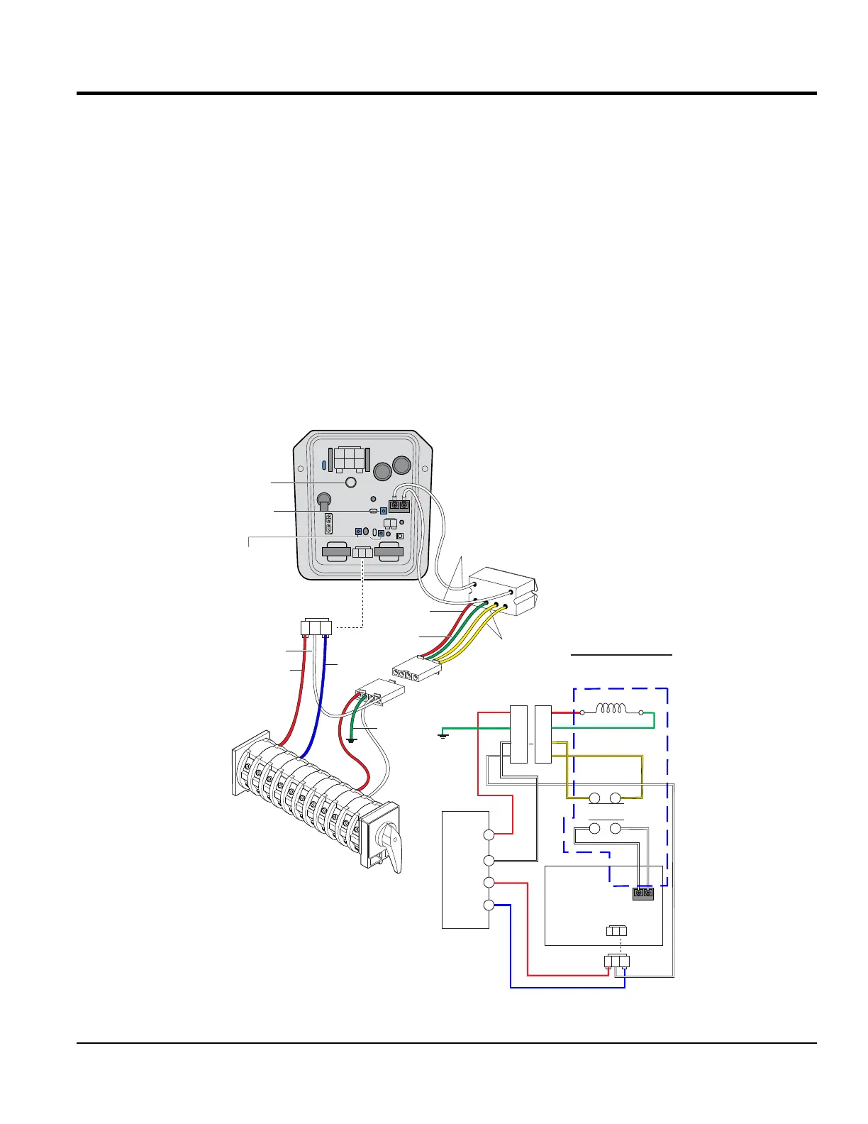
As shown in Figure 52 there are three outside connectors
that plug into the CN1, CN3 and CN4 receptacles on the
AVR.
The CN2 receptacle has no outside plug connected to it.
Pins 1 and 2 are internally jumpered together and pins 3
and 4 are also jumpered together.
As shown in Figure 52 there are two WHITE wires that
connect to the AVR 2-pin terminal block via relay unit RY1.
The AVR also has three potentiometers only one is used
for coarse adjustment of the voltage, the other two are
factory set and should NOT be adjusted. In addition there
is an 8-amp circuit protection fuse.
AVR INTERNAL SENSING (CN3)
The CN3 connector (Figure 52) is used for the internal
sensing of the AVR.
U-phase wire is RED and is connected to terminal #14
on the voltage selector switch.
V-phase wire is WHITE and is connected to V-Leg on
Relay Unit (RY1).
W-phase wire is BLUE and is connected to terminal #36
on the voltage selector switch.
AUTOMATIC VOLTAGE REGULATOR
Figure 52. AVR Internal Sensing
(-)
2
1
A J C
DKB
3
CN1
CN2
CN3
CN4
2 1
13
WHITE
WIRE (2)
CN6
RED
GREEN
#42
GREEN
RELAY
UNIT (RY1)
(+)
#26
U V W
1 2 3
3
2 1
RED
WHITE
BLUE
#14
#36
YELLOW
AVR
COIL
RED
CN6
RELAY
UNIT (RY1)
1
2
3
4
1
2
3
4
2
1
3
4
AVR
VSS
VOLTAGE SELECTOR
SWITCH (VSS)
TB1
1 2
1 2
NO
26
CN3
(PLUG)
U V W
1 2 3
TB1
3
2 1
CN3
(PLUG)
14
36
42
GND.
RED
GREEN
GREEN
YELLOW
YELLOW
WHITE
WHITE
NC
BLUE
RED
WHITE
WHITE
V2
V2
V2
V2
V2
V2
CN3
(RECEPTACLE)
COARSE
VOLTAGE ADJ.
POTENTIOMETER
FACTORY SET
POTENTIOMETERS
DO NOT ADJUST
GND.
WIRING DIAGRAM
8 AMP
FUSE
WHITE