PAGE 42 — GENERATOR SERVICE AND TROUBLESHOOTING MANUAL — REV. #0 (08/29/23)
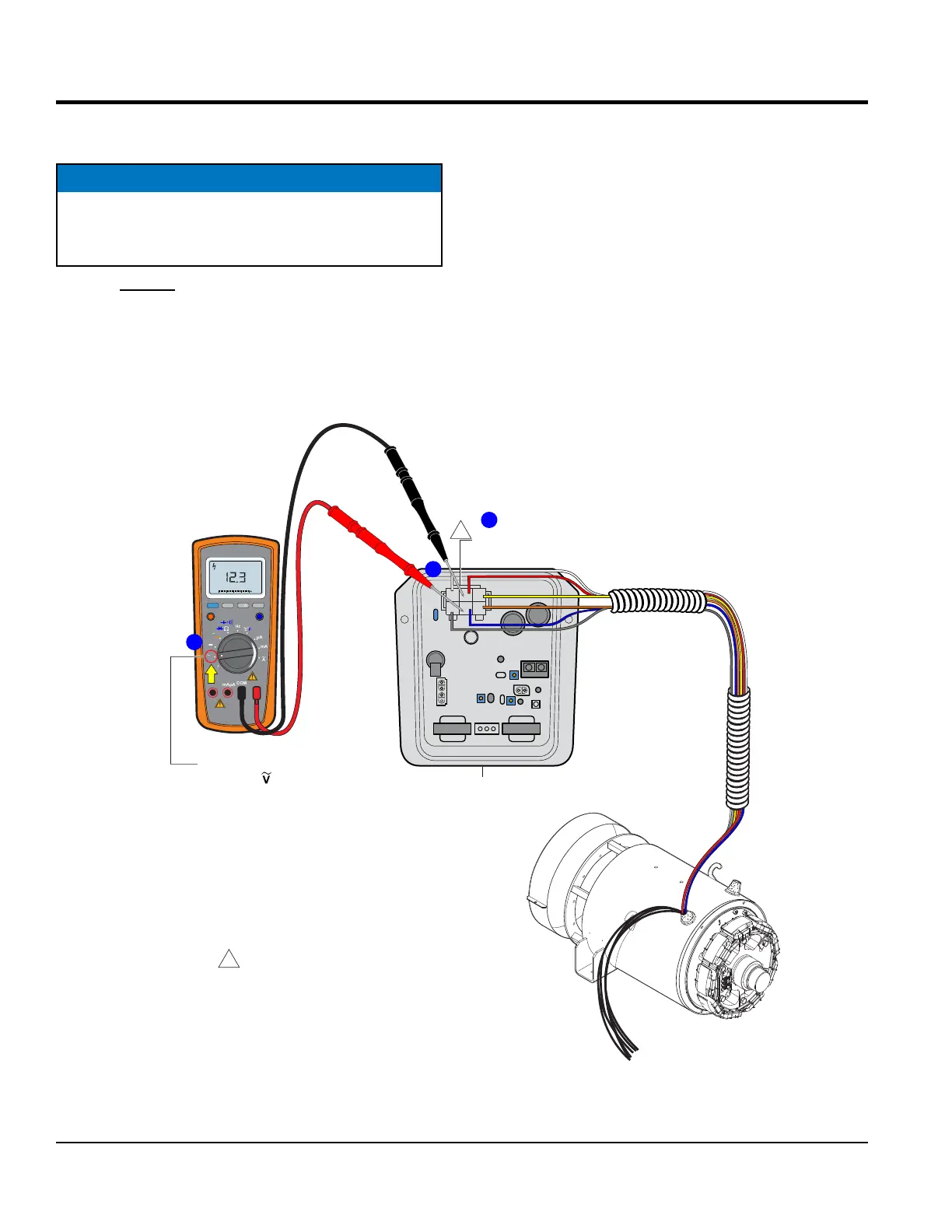
EXCITER FIELD VOLTAGE MEASUREMENT
(
NO LOAD
)
EXCITER FIELD VOLTAGE MEASUREMENT
(NO LOAD)
1. With no load applied start the engine as referenced
in the operation manual.
2. The voltage selector switch or voltage change-
overboard can be congured in any position or setting.
NOTICE
Use extreme caution when performing this test. The
possibility exist of electrical shock which could cause
severe bodily harm.
3. Next, open the control panel door on the generator and
locate the 6-pin plug (Figure 43A) on the AVR.
4. Set the selection dial on the multimeter to AC volts
(Figure 43B).
5. Place the multimter test leads arcoss pins J and K
on the 6-pin plug as shown in Figure 43C. Multimeter
probe extenders are recommend for easy access to
the connector pins.
6. Verify that the exciter eld voltage (no load) reading
is within range as referenced in Table 7 , column C.
Figure 43. Exciter Field Voltage Measurement (No Load)
CN1
CN2
CN3
CN4
EXAMPLE:
DCA-25SSIU4F = 12.3 VAC
6-PIN
PLUG
2
C J A
BKD
1
3
YELLOW
WHITE
ORANGE
GRAY
BLUE
RED
AVR
REAR VIEW
WIRE SIDE
1
1
NOTES:
WIRE COLOR SHOWN IS FOR
A DCA-25SSIU4F GENERATOR.
ALL OTHER DCA GENERATORS
USE BLACK WIRES.
RANGE
MIN MAX
MULTIMETER
Auto0 600
OFF
Hz
C
A
mA
uA
F
V
Hz
V
mV
Hz %REL
HOLD/LIGHT
10 A
MAX
mAµA
COM
V
AC
MULTIMETER
PROBE EXTENDERS
A
C
B
TURN
SELECTION
DIAL TO
POSITION