GENERATOR SERVICE AND TROUBLESHOOTING MANUAL — REV. #0 (08/29/23) — PAGE 49
MAIN CIRCUIT BREAKER
MAIN CIRCUIT BREAKER
The main circuit breaker (Figure 54) connects and
disconnects the generator output voltage from the U, V,
W output terminal lugs.
Most of the circuit breaker (CB) trip faults are due to
insufcient sizing of the generator to the load. It is essential
that the unit being used for the application be sized properly
to the load in order to prevent these types of nuisance .
Reference Table 2.
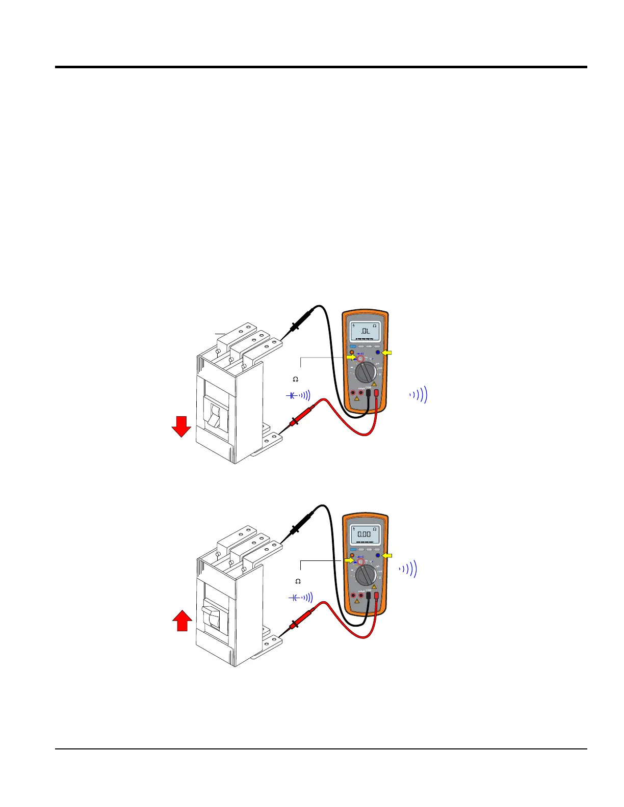
With the generator OFF, place the circuit breaker (Figure 54)
in the OFF position. Set the multimeter selection dial to to
the W position, then select the sound icon.
Next, verify that there is no continuity (no beep!) between
the L1, L2 and L3 inputs and output contacts of the
breaker (top and bottom). This implies an OPEN circuit,
no continuity (good).
Repeat the above test with the circuit breaker in the ON
position. Verify that there is continuity (beep! beep!)
between the input and output contacts of the breaker. This
implies a CLOSED circuit, continuity. Reference Table 2
for the amperage characteristics of the breaker installed
on the specied generator.
Figure 54. Circuit Breaker Continuity Test
MULTIMETER
NO BEEP!
INPUT
OUTPUT
3-POLE
CIRCUIT
BREAKER
OPEN CIRCUIT
L1
L2
L3
MULTIMETER
BEEP!
BEEP! BEEP!
INPUT
OUTPUT
CLOSED CIRCUIT
L1
L2
L3
OFF
OFF
NO CONTINUITY
CONTINUITY
CONTACTS
ON
ON
TURN SELECTION
DIAL TO POSITION
SELECT SOUND ICON
RANGE
MIN MAX
MULTIMETER
Auto0 600
OFF
Hz
C
A
mA
uA
F
V
Hz
V
mV
Hz %REL
HOLD/LIGHT
10 A
MAX
mAµA
COM
RANGE
MIN MAX
MULTIMETER
Auto0 600
OFF
Hz
C
A
mA
uA
F
V
Hz
V
mV
Hz %REL
HOLD/LIGHT
10 A
MAX
mAµA
COM
TURN SELECTION
DIAL TO POSITION
SELECT SOUND ICON