PAGE 20 — GENERATOR SERVICE AND TROUBLESHOOTING MANUAL — REV. #0 (08/29/23)
ELECTRICAL INSPECTION
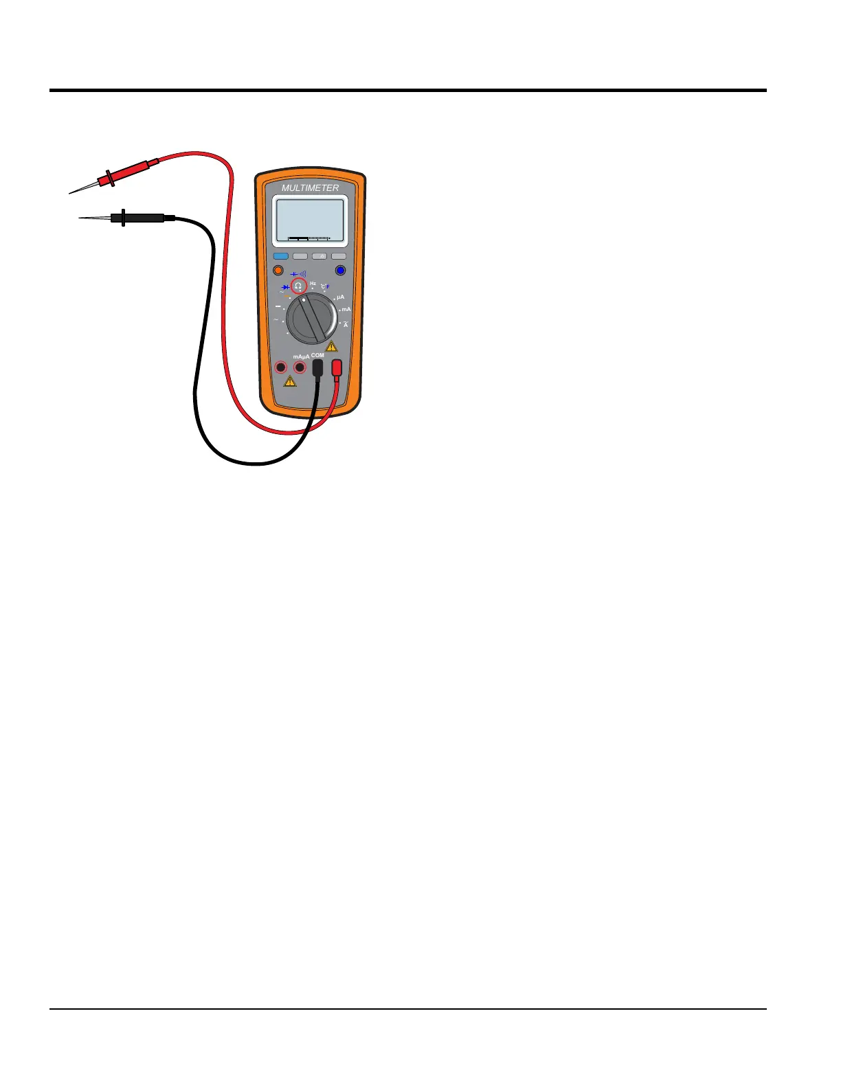
When servicing generators, having an accurate AC/DC
multimeter is a must (Figure 13).
Figure 13. AC/ DC Multimeter
ELECTRICAL INSPECTION
The rst step in generator troubleshooting is to conduct
a visual inspection before doing any electrical tests.
Looking over the generator carefully should expose any
environmental factors that might contribute to the problem.
As you remove the generator control box cover and begin
your inspection, look for the following:
Electrical Connections — Rusted, corroded and oxidized
connections will prevent the circuit from being completed.
This applies not only to the major cables externally, but
also to the electronic control devices internally.
Carbon Flash — If the AC receptacles on the generator
have ever been shorted, carbon ash deposits around the
120/240V AC receptacles may appear. This will indicate
whether the device that was plugged into the generator
shorted out the receptacle. The device may have shorted
the generator to ground and caused a carbon ash when
the plug prongs touched the receptacle.
Wire Overheating — Signs of wire overheating
(discoloration and a burnt smell) should be noticeable
inside the generator. Look to see if the windings turned
black. The winding insulative coating may vary in color from
shades of reddish brown to light brown to dark brown, so
try to compare the color to that of a new unit.
RANGE
MIN MAX
MULTIMETER
Auto0 600
OFF
Hz
C
A
mA
uA
F
V
Hz
V
mV
Hz %REL
HOLD/LIGHT
10 A
MAX
mAµA
COM
Infestation — Insects and rodents may have created a nest
inside the generator. These nests and associated debris
can cause electrical shorts. Generators left out in remote
areas provide a home for spiders, wasps other insects and
mice. Always inspect the generator daily.
Hardware — Loose hardware will shorten the life cycle
of the generator and decrease the overall performance of
the generator.
Terminal Lugs/Bus Bars — Always make sure all nuts,
bolts, screws, and fasteners are securely tightened.
DO NOT over tighten. Reference Torque Specications
(Table 9). Look for any elongation on the bolt hole opening
on the buss bar.
Electrical Connectors — Sometimes electrical connectors
do not always make a good connection. Always make
sure the electrical connectors are seated correctly. Some
electrical connectors may have more than a dozen
male-female connections.
These are often inside some plastic or rubber cover
that prevents you from seeing any possible corrosion.
In electrical troubleshooting, always unplug and plug
all connectors three times to produce a freshly scraped
metallic surface for good electrical contact.
Using an ohmmeter, check for zero ohms on all
connections. Spray the contacts with an electrical insulative
spray before reassembling them.
Crimp Connections — Even though they are widely used,
they can become loose as the machine vibrates and lose
consistent quality contact. Because dissimilar metals are in
contact, a galvanic cell is set up that may result in corrosion
when moisture is present.
Solder Joints — Solder joints that have cracked or broken
loose. This condition occurs much less frequently than
crimped connections and basically results from poor-quality
workmanship.
Wire Identication — Verify all unmarked wiring and
correct, particularly if the unit comes from another shop with
unresolved issues or you receive it partially disassembled.
Circuit Safety Devices — Check for physical damage to
housing, buttons and levers on all fuses, circuit breakers,
and ground fault interrupters.