PAGE 36 — GENERATOR SERVICE AND TROUBLESHOOTING MANUAL — REV. #0 (08/29/23)
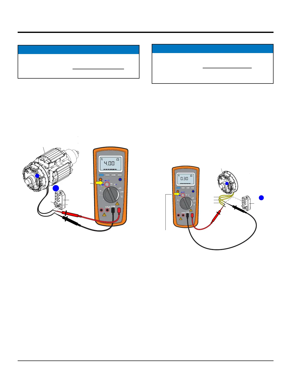
MAIN FIELD RESISTANCE TEST
The main eld (Figure 36) consists of two black lead
wires with no wire designation. These two wire leads are
connected to the DC positive and DC negative terminals
on the rotating rectier in conjunction with the surge
protector.
Figure 36. Main Field Resistance Test
Using a multimeter (Figure 36), check the resistance across
each black wire as referenced in Table 6, column B. Be
sure to place the selection dial on the multimeter to the
Ω position. If the reading indicates an open circuit the
component may have to be replaced or repaired.
NOTICE
Before performing the resistance test, the two black
lead wires (Figure 36) must be disconnected from
the rotating rectier.
RANGE
MIN MAX
MULTIMETER
Auto0 600
OFF
Hz
C
A
mA
uA
F
V
Hz
V
mV
Hz %REL
HOLD/LIGHT
10 A
MAX
mAµA
COM
ROTATING
RECTIFIER
NO WIRE
DESIG.
WIRE
COLOR
BLACK (2)
A
U
V
W
TURN
SELECTION
DIAL TO Ω
POSITION
EXAMPLE:
DCA-25SSIU4F = 4.0Ω
MAIN
FIELD
U
V
W
A
UNSOLDER
WIRE LEADS
FROM ROTATING
RECTIFIER
DC
POS.
DC
NEG.
MULTIMETER
EXCITER ARMATURE RESISTANCE TEST
The exciter armature (Figure 37) consists of three yellow
lead wires with no wire designation. These three wire leads
are connected to the U, V and W terminals on the rotating
rectier.
Using a multimeter (Figure 37), check the resistance across
each pair of wires as referenced in Table 6, column C. Be
sure to place the selection dial on the multimeter to the
Ω position.
Figure 37. Exciter Armature Resistance Check
NOTICE
Before performing the resistance test, the three yellow
lead wires (Figure 37) must be disconnected from the
rotating rectier. If the reading indicates an open circuit
the component may have to be replaced or repaired.
RANGE
MIN MAX
MULTIMETER
Auto0 600
OFF
Hz
C
A
mA
uA
F
V
Hz
V
mV
Hz %REL
HOLD/LIGHT
10 A
MAX
mAµA
COM
MULTIMETER
EXCITER
STATOR
ROTATING
RECTIFIER
NO WIRE
DESIG.
WIRE
COLOR
YELLOW (3)
W
V
U
U
V
W
A
A
UNSOLDER
WIRE LEADS
FROM ROTATING
RECTIFIER
U
V
W
TURN
SELECTION
DIAL TO Ω
POSITION
MEASURE
W TO V
W TO U
V TO U
= 0.30Ω
EXAMPLE:
DCA-25SSIU4F = 0.30Ω
MAIN FIELD/EXCITER ARMATURE RESISTANCE TEST