PAGE 46 — GENERATOR SERVICE AND TROUBLESHOOTING MANUAL — REV. #0 (08/29/23)
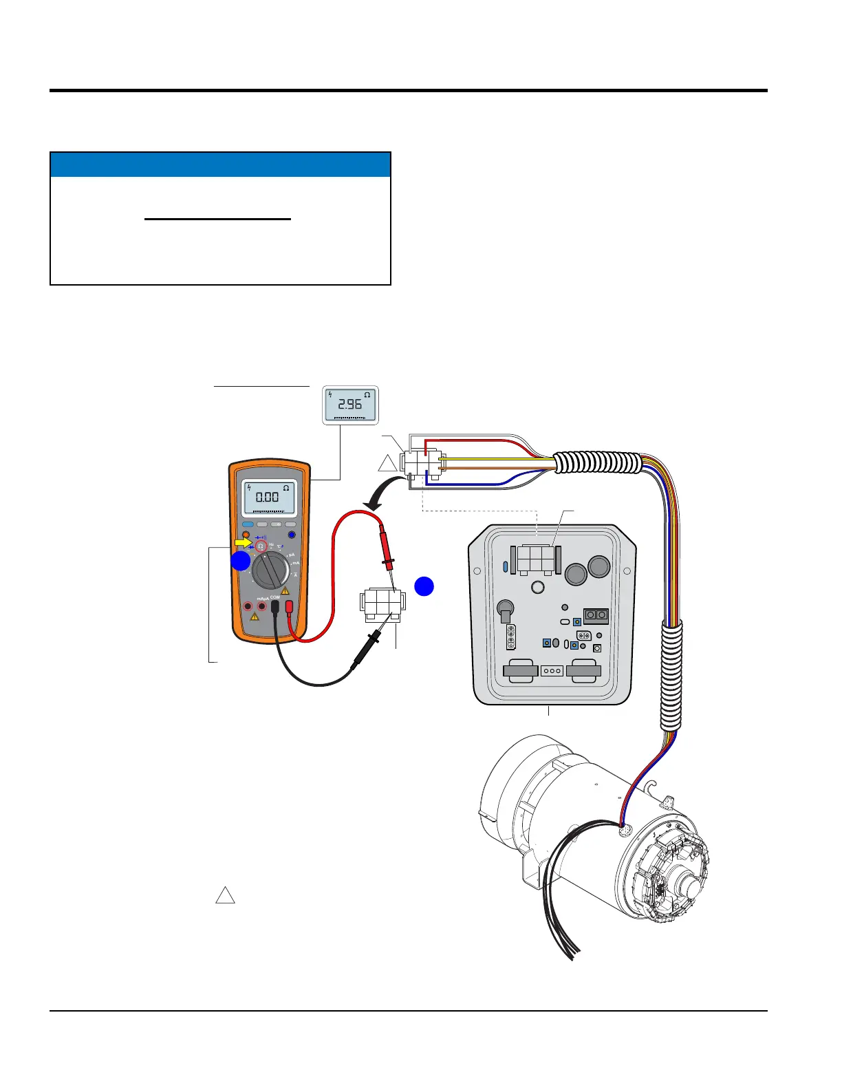
MAIN ARMATURE AVR INPUTS RESISTANCE CHECK
MAIN ARMATURE AVR INPUTS RESISTANCE
CHECK (CN1)
NOTICE
Before performing the resistance check, the 6-pin plug
(Figure 51B) must be disconnected from the CN1
receptacle on the AVR. If the reading indicates an
open circuit the component may have to be replaced
or repaired.
Figure 51. Main Armature AVR Inputs Resistance Check
EXAMPLE:
DCA-25SSIU4F
TURN
SELECTION
DIAL TO Ω
POSITION
2
C J A
BKD
1
3
YELLOW
WHITE
ORANGE
GRAY
BLUE
RED
AVR
6-PIN
PLUG
2
C J A
BKD
1
3
6-PIN
PLUG
2
1
A J C
DKB
3
CN1
CN2
CN3
CN4
RECEPTACLE
REAR VIEW
WIRE SIDE
5 4
6
1
1
NOTES:
WIRE COLOR SHOWN IS FOR
A DCA-25SSIU4F GENERATOR.
ALL OTHER DCA GENERATORS
USE BLACK WIRES.
DISCONNECT
MEASURE
A TO B
C TO D
D TO A
= 1.03Ω
MEASURE
B TO C
= 2.96Ω
RANGE
MIN MAX
MULTIMETER
Auto0 600
OFF
Hz
C
A
mA
uA
F
V
Hz
V
mV
Hz %REL
HOLD/LIGHT
10 A
MAX
mAµA
COM
A
Auto0 600
B
Set the multimeter selection dial to the W position as shown
in Figure 51A.
Next, check the resistance across the A-B, C-D, D-A open
delta wire leads as referenced in Figure 51B. Compare
measured reading to values listed in Table 6, column E.
Finally, check the resistance across the B-C open delta
wire leads as referenced in Figure 51B. Compare measured
reading to values listed in Table 6, column F.
Again, be sure to unplug the 6-pin plug from the CN1
receptacle on the AVR.