PAGE 38 — GENERATOR SERVICE AND TROUBLESHOOTING MANUAL — REV. #0 (08/29/23)
MANUAL EXCITATION FIELD VOLTAGE TEST
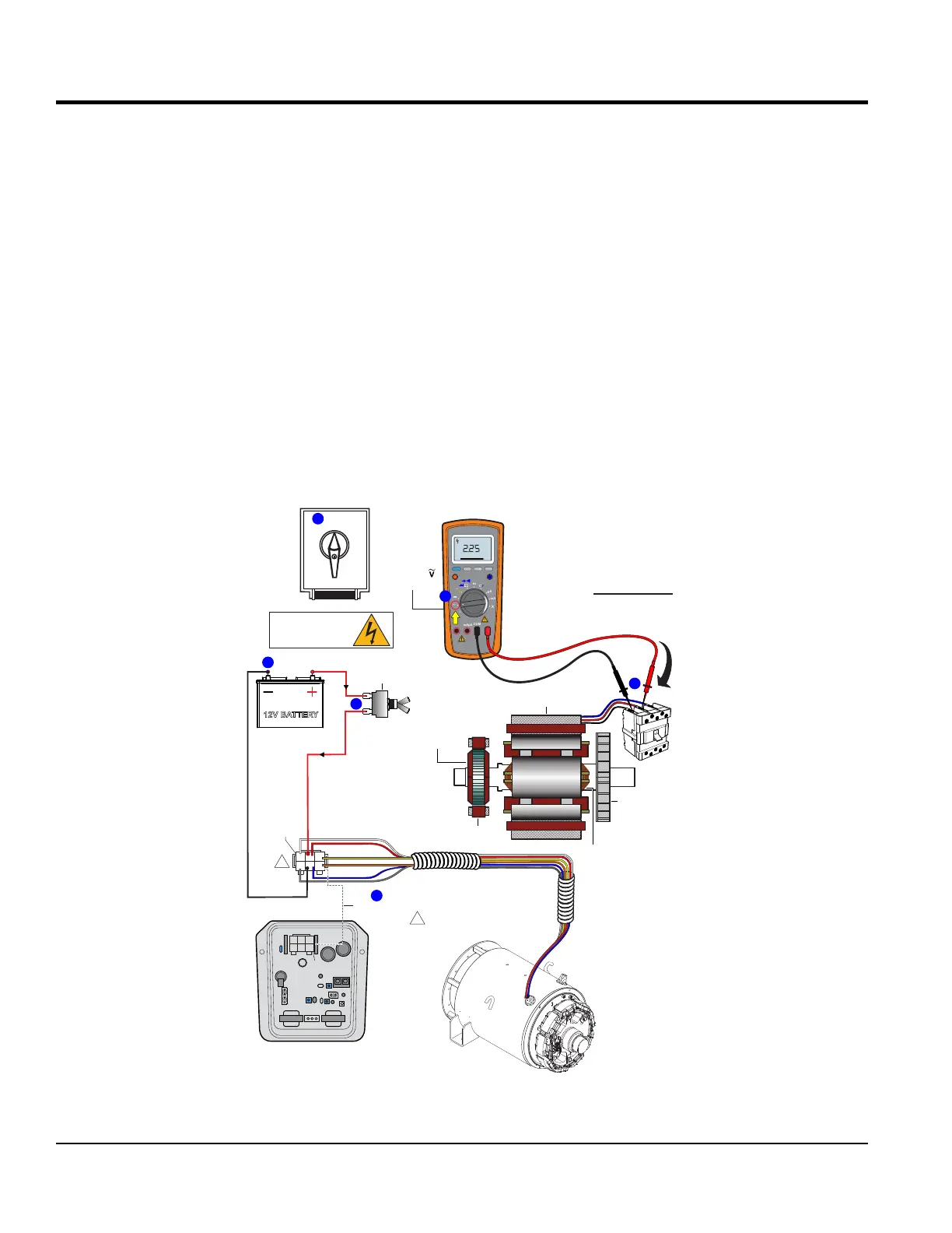
MANUAL EXCITATION TEST (3-PHASE VOLTAGE)
1. With the engine OFF, place the voltage selector
switch (Figure 39A) in the 3-Phase, 240/139V position.
2. Unplug the 6-pin plug from the CN1 receptacle on the
AVR (Figure 39B).
3. Connect a SPST toggle switch (Figure 39C) between
the positive battery terminal and pin J on the 6-pin plug.
4. Connect a wire from the negative battery terminal to
pin K on the 6-pin plug (Figure 39D).
5. Place toggle switch in the OFF (open) position, if
equipped set engine speed switch to the low position
(idle). Start the engine and then place toggle switch in
ON position (closed).
6. Next, place engine speed switch in the high position
and run the engine at full rpm.
7. Place the selection dial on the multimeter to the AC
volts position (Figure 39E).
8. Using a multimeter, measure voltage at the U, V and
W terminals (Figure 39F) located on top of the main
circuit breaker (line side).
9. Take both phase-to-phase and phase-to-neutral
readings. Compare readings as referenced in Table 7,
column E. Verify voltage reading is balanced phase to
phase and phase to neutral.
Figure 39. Manual Excitation Test Three-Phase Voltage
3 PHASE
480/277
1 PHASE
240/120
3 PHASE
240/139
PRESS TO LOCK
SPST
TOGGLE
SWITCH
OFF
ON
EXAMPLE:
DCA-25SSIU4F
A
U ~ V = 212 V
THREE PHASE
VOLTAGE @ 60 Hz
TEST CHART
V ~ W = 212 V
W~ U = 212 VAC
D
TURN
SELECTION
DIAL TO
POSITION
2
1
A J C
DKB
3
CN1
CN2
CN3
CN4
2
C J A
B
K
D
1
3
YELLOW
WHITE
ORANGE
GRAY
BLUE
RED
6-PIN PLUG
WIRE SIDE
1
DISCONNECT
U
V
W
3-POLE
CIRCUIT
BREAKER
FAN
EXCITER
STATOR
MAIN
STATOR
MAIN FIELD
ROTOR
EXCITER
ARMATURE
RECEPTACLE
5
4
6
AVR
STATOR
FRAME
B
1
NOTES:
WIRE COLOR SHOWN IS FOR
A DCA-25SSIU4F GENERATOR.
ALL OTHER DCA GENERATORS
USE BLACK WIRES.
C
F
12V BATTERY
DANGER!
ELECTRIC SHOCK
(Live Terminals)
RANGE
MIN MAX
MULTIMETER
Auto0 600
OFF
Hz
C
A
mA
uA
F
V
Hz
V
mV
Hz %REL
HOLD/LIGHT
10 A
MAX
mAµA
COM
V
AC
E