PAGE 40 — GENERATOR SERVICE AND TROUBLESHOOTING MANUAL — REV. #0 (08/29/23)
EXCITER FIELD CURRENT MEASUREMENT
(
NO LOAD
)
EXCITER FIELD CURRENT MEASUREMENT
(NO LOAD)
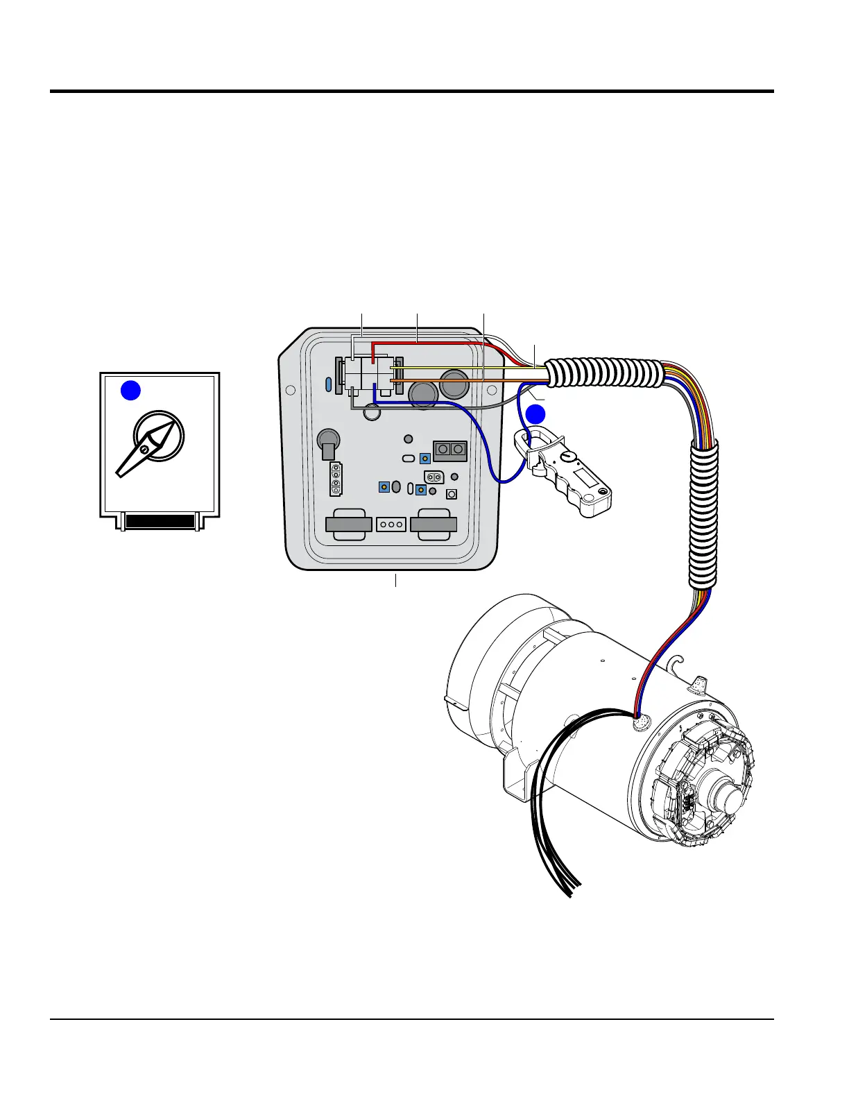
1. With the engine OFF, place the voltage selector
switch (Figure 41A) in the 1-Phase, 240/120V position.
2. If equipped, set engine speed switch to the low position
(idle).
3. Start the engine.
4. If equipped, place engine speed switch in the high
position and run the engine at full rpm.
5. Place ammeter clamp around pin K on the 6-pin plug
as shown in Figure 41B.
6. Verify that the exciter eld amperage (no load) reading
is within range as referenced in Table 7 , column A.
Figure 41. Exciter Field Current Measurement (No Load)
CN1
CN2
CN3
CN4
EXAMPLE:
DCA-25SSIU4F
2
C J A
BKD
1
3
YELLOW
WHITE
GRAY
BLUE
AVR
ORANGE
RED
AMMETER CLAMP
CONNECT TO PIN K
ON CN1/CN5
CN5
3 PHASE
480/277
1 PHASE
240/120
3 PHASE
240/139
PRESS TO LOCK
A
MEASURE .067 AMPS
B