GENERATOR SERVICE AND TROUBLESHOOTING MANUAL — REV. #0 (08/29/23) — PAGE 41
EXCITER FIELD CURRENT MEASUREMENT
(
WITH LOAD
)
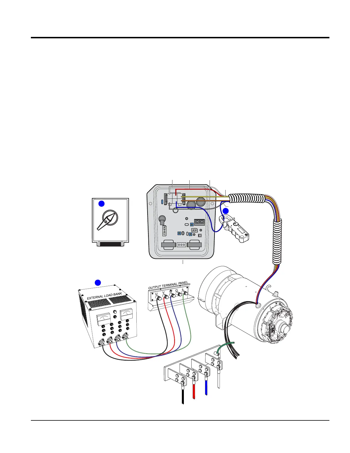
EXCITER FIELD CURRENT MEASUREMENT
(WITH LOAD)
1. With the engine OFF, place the voltage selector
switch (Figure 42A) in the 1-Phase, 240/120V position.
2. If equipped, set engine speed switch to the low position
(idle).
3. Connect an external load bank to the output terminal
panel or buss bars on the generator as shown in
Figure 42B.
4. Congure load bank for the specied rated load as
referenced in the data sheet. This example will use
a load rating of 20 kW/25 kVA for a DCA25SSIU4F
generator.
5. Start the engine.
6. If equipped, place engine speed switch in the high
position and run the engine at full rpm.
7. Place ammeter clamp around pin K on the 6-pin plug
as shown in Figure 42C.
8. Verify that the exciter eld amperage (with load) reading
is within range as referenced in Table 7 , column B.
Figure 42. Exciter Field Current Measurement (With Load)
USED ON DCA600
GENERATORS AND ABOVE
USED ON DCA400
GENERATORS AND BELOW
CN1
CN2
CN3
CN4
EXAMPLE:
DCA-25SSIU4F
2
C J A
BKD
1
3
YELLOW
WHITE
GRAY
BLUE
AVR
ORANGE
RED
AMMETER CLAMP
CONNECT TO PIN K
ON CN1/CN5
6-PIN PLUG
3 PHASE
480/277
1 PHASE
240/120
3 PHASE
240/139
PRESS TO LOCK
A
MEASURE 1.92 AMPS
C
3-PHASE
B
U
V
W
GND.
BLACK
RED
O
WHITE
GREEN
BLUE
BUSS BARS