GENERATOR SERVICE AND TROUBLESHOOTING MANUAL — REV. #0 (08/29/23) — PAGE 67
MAGNETIC PICKUP UNIT
MAGNETIC PICK UP (MPU)
The magnetic pick-up (MPU) is an electromagnetic sensor
and is mounted in the ywheel bell housing of the engine.
When a tooth from the engine ywheel passes under the
tip of the sensor, electrical impulses are induced within the
coil of the MPU and transmitted to the electronic control
module (ECM).
This electrical impulse signal is expressed in hertz (Hz)
and is directly proportional to the engine speed. The ECU
uses this signal to determine engine speed.
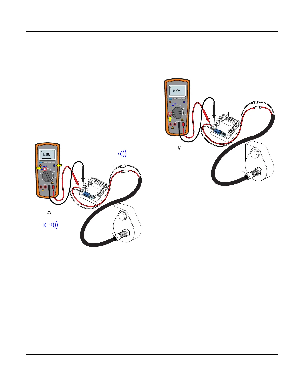
MPU Continuity Test
1. Place the multimeter test leads across pins 1 and 2 on
the ECU auto start module as shown in Figure 73.
Figure 73. MPU Continuity Test
2. Set the multimeter selection dial to the sound position
and verify that there is continuity (beep!) between the
pin 1 (BLACK/WHITE) and pin 2 (RED) wire leads on
the ECU auto start module as referenced in Figure 73.
3. If the multimeter reads OPEN (no continuity or beep),
replace the MPU sensor.
MPU SENSOR
WIRE LEADS
MEASURE
CONTINUITY
MULTIMETER
SENSOR
PLATE
BLK/WHT
BEEP! BEEP! BEEP!
RED
ECU
AUTO-START
MODULE
O
N
1
2
3
4
5
1
2
MPU
SENSOR
RANGE
MIN MAX
MULTIMETER
Auto0 600
OFF
Hz
C
A
mA
uA
F
V
Hz
V
mV
Hz %REL
HOLD/LIGHT
10 A
MAX
mAµA
COM
TURN SELECTION
DIAL TO POSITION
SELECT SOUND ICON
MPU AC Voltage Test
1. With the multimeter test leads still placed across
pins 1 and 2 on the ECU auto-start module, set the
multimeter selection dial to the AC Volts position
(Figure 74).
Figure 74. MPU Voltage Test
2. Now crank the engine (engine will not start) and verify
that the multimeter reads between 2.25 VAC ± 0.50
3. If a low voltage reading is obtained, reference the "MPU
Installation and Adjustment" section.
MPU SENSOR
WIRE LEADS
MULTIMETER
MEASURE
2.25± 0.50 VAC
SENSOR
PLATE
BLK/WHT
RED
ECU
AUTO-START
MODULE
TURN
SELECTION
DIAL TO
POSITION
MPU
SENSOR
O
N
1
2
3
4
5
1
2
RANGE
MIN MAX
MULTIMETER
Auto0 600
OFF
Hz
C
A
mA
uA
F
V
Hz
V
mV
Hz %REL
HOLD/LIGHT
10 A
MAX
mAµA
COM
V
AC