GENERATOR SERVICE AND TROUBLESHOOTING MANUAL — REV. #0 (08/29/23) — PAGE 23
COMPONENT IDENTIFICATION
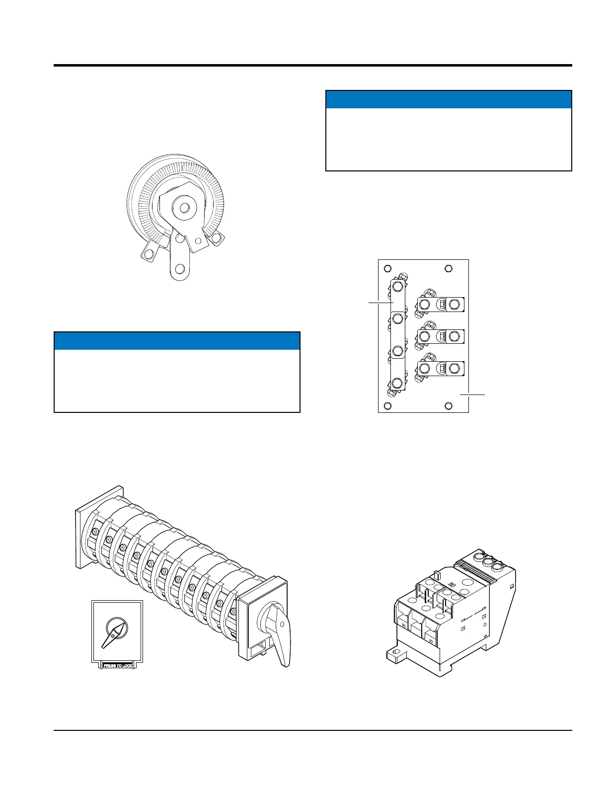
RHEOSTAT (VR)
The rheostat (Figure 16) is a variable resistor (VR)
connected directly to the AVR and is used for ne tuning
output voltage.
Figure 16. Rheostat (VR)
VOLTAGE SELECTOR SWITCH
The voltage selector switch (Figure 17) is used to congure
the generator coils for the selected voltage output by
reconguring the internal contacts of the switch each time
a voltage selection is made.
Figure 17. Voltage Selector Switch
NOTICE
The voltage selector switch is only used on
DCA 150 model generators and below. DCA 180 model
generators and above use a voltage change-over
board. Reference Figure 18.
3 PHASE
480/277
3 PHASE
240/139
1 PHASE
240/120
PRESS TO LOCK
VOLTAGE CHANGE-OVER BOARD
The voltage change-over board (Figure 18) is used to
congure the generator coils for the selected voltage output
by arranging jumper plates onto the change-over board to
obtain various voltage output congurations.
Figure 18. Voltage Change-Over Board
OVERCURRENT RELAY (THERMAL OVERLOAD)
The overcurrent relay (OCR) is connected to the main
circuit breaker and monitors current to the output terminals
via the current transformers. In the event of an overload or
short circuit it will electronically trip the main circuit breaker.
Figure 19. Overcurrent Relay
NOTICE
The voltage change-over board (Figure 18) is only
used on DCA 180 model generators and above.
DCA 150 model generators and below use a voltage
selector switch. Reference Figure 17.
JUMPER
PLATES (6)
VOLTAGE
CHANGE-OVER
BOARD
SHOWN JUMPER PLATE
CONFIGURATION IS
FOR:
3Ø 240/139 VAC
OUTPUT TERMINAL PANEL
WILL PROVIDE:
3Ø 240, 220 AND 208 VAC
1Ø 240, 220 AND 208 VAC
1Ø 139, 127 AND 120 VAC