PAGE 24 — GENERATOR SERVICE AND TROUBLESHOOTING MANUAL — REV. #0 (08/29/23)
MAIN CIRCUIT BREAKER (CB1)
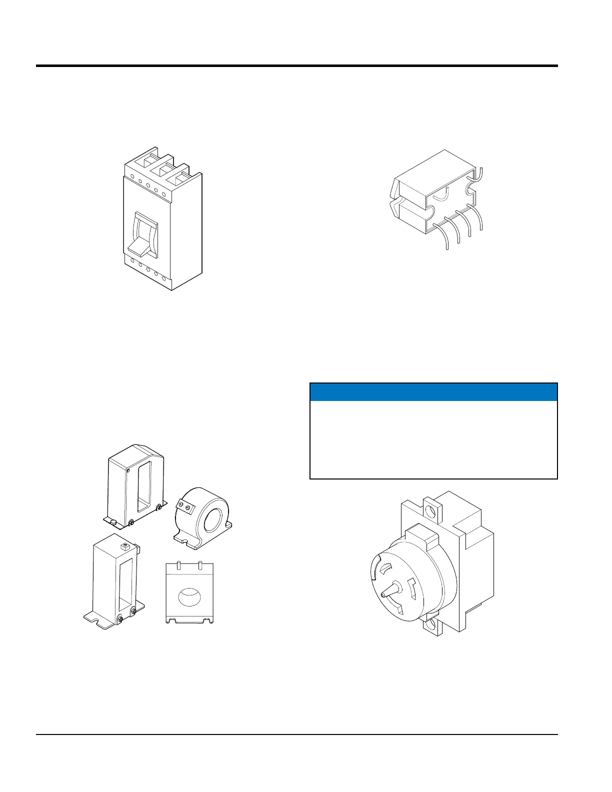
The main circuit breaker (Figure 20) commonly referenced
as CB1, protects the generator output terminals U V W from
overload.
Figure 20. Main Circuit Breaker (CB1)
CURRENT TRANSFORMER (CT)
Figure 21 shows some of the different types of current
transformers installed in the generators.These current
transformers (CT1, 2, 3) sense the output current supplied
by the generator and are connected to the ammeter and
the OCR.
Figure 21. Current Transformers
COMPONENT IDENTIFICATION
RELAY UNIT (RY1)
The relay unit (Figure 22) disconnects the V-leg at the
AVR and AC voltmeter when the voltage selector switch
has been placed in the 120/240 single-phase position.
Figure 22. Relay Unit
TWIST-LOCK RECEPTACLE (CS-6369)
For DCA 150 model generators and below the voltage
selector switch (Figure 17) must be placed in the
single-phase, 120/240V position, and the main circuit
breaker closed in order to use the 120/240V, 50-amp
twist-lock receptacle (Figure 23).
Figure 23. Twist-Lock Receptacle
NOTICE
For DCA 180 model generators and above the voltage
change-over board (Figure 18) must be congured
for the single-phase, 120/240V application in order
to use the 120/240V, 50-amp twist-lock receptacle
(Figure 23).