GENERATOR SERVICE AND TROUBLESHOOTING MANUAL — REV. #0 (08/29/23) — PAGE 45
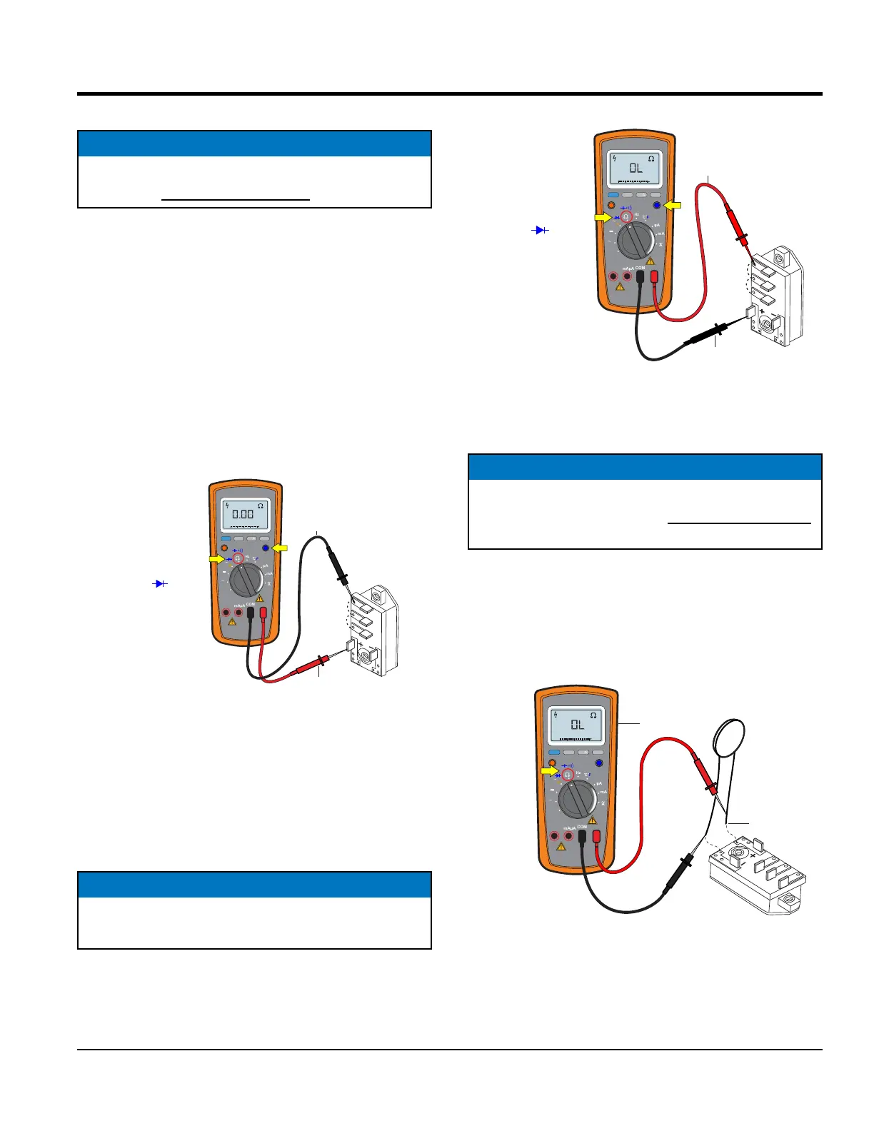
ROTATING RECTIFIER TEST
The rotating rectier is connected to both the main eld
and exciter armature and is mounted on the exciter stator
armature.
Be sure to place the selection dial on the multimeter in
the diode position. Sometimes referenced as the diode
feature test.
Place the positive lead from the multimeter on the DC
POSTIVE (+) terminal of the rectier (Figure 48). Now touch
the U, V and W terminals one at a time with the NEGATIVE
(–) lead. Each terminal should give a continuity reading.
Figure 48. Rotating Rectier Check (Positive)
Reverse the multimeter leads. Place the NEGATIVE lead
of the multimeter on the DC Positive (+) terminal of the
rectier (Figure 49) and touch U, V and W terminals with
the positive lead. This should cause the multimeter to read
open circuit.
NOTICE
Before performing the continuity test, all lead wires
(Figure 48) must be disconnected from the rectier.
U
V
W
ROTATING
RECTIFIER
NEGATIVE
LEAD
POSITIVE
LEAD
RANGE
MIN MAX
MULTIMETER
Auto0 600
OFF
Hz
C
A
mA
uA
F
V
Hz
V
mV
Hz %REL
HOLD/LIGHT
10 A
MAX
mAµA
COM
TURN
SELECTION
DIAL TO Ω POSITION
SELECT ICON
NOTICEa
If the rotating rectier fails any of the tests as referenced
in Figure 48 or Figure 49, replace the rectier.
ROTATING RECTIFIER TEST
Figure 49. Rotating Rectier Check (Negative)
SURGE PROTECTOR CHECK (DCA125-150)
Place the selection dial on the multimeter in the Ω position.
Next, place the multimeter leads across the surge protector
as shown in Figure 50 and verify that the meter displays an
open circuit. If the meter indicates continuity or another
reading, replace the surge protector.
Figure 50. Surge Protector Check
U
V
W
ROTATING
RECTIFIER
POSITICE
LEAD
NEGATIVE
LEAD
RANGE
MIN MAX
MULTIMETER
Auto0 600
OFF
Hz
C
A
mA
uA
F
V
Hz
V
mV
Hz %REL
HOLD/LIGHT
10 A
MAX
mAµA
COM
TURN
SELECTION
DIAL TO Ω POSITION
SELECT ICON
OPEN
CIRCUIT
NOTICE
Before performing the continuity check, both surge
protector lead wires (Figure 50) must be disconnected
from the rotating rectier.
U
V
W
SURGE
PROTECTOR
UNSOLDER
LEADS
OPEN
CIRCUIT
ROTATING
RECTIFIER
RANGE
MIN MAX
MULTIMETER
Auto0 600
OFF
Hz
C
A
mA
uA
F
V
Hz
V
mV
Hz %REL
HOLD/LIGHT
10 A
MAX
mAµA
COM
TURN
SELECTION
DIAL TO Ω
POSITION