PAGE 48 — GENERATOR SERVICE AND TROUBLESHOOTING MANUAL — REV. #0 (08/29/23)
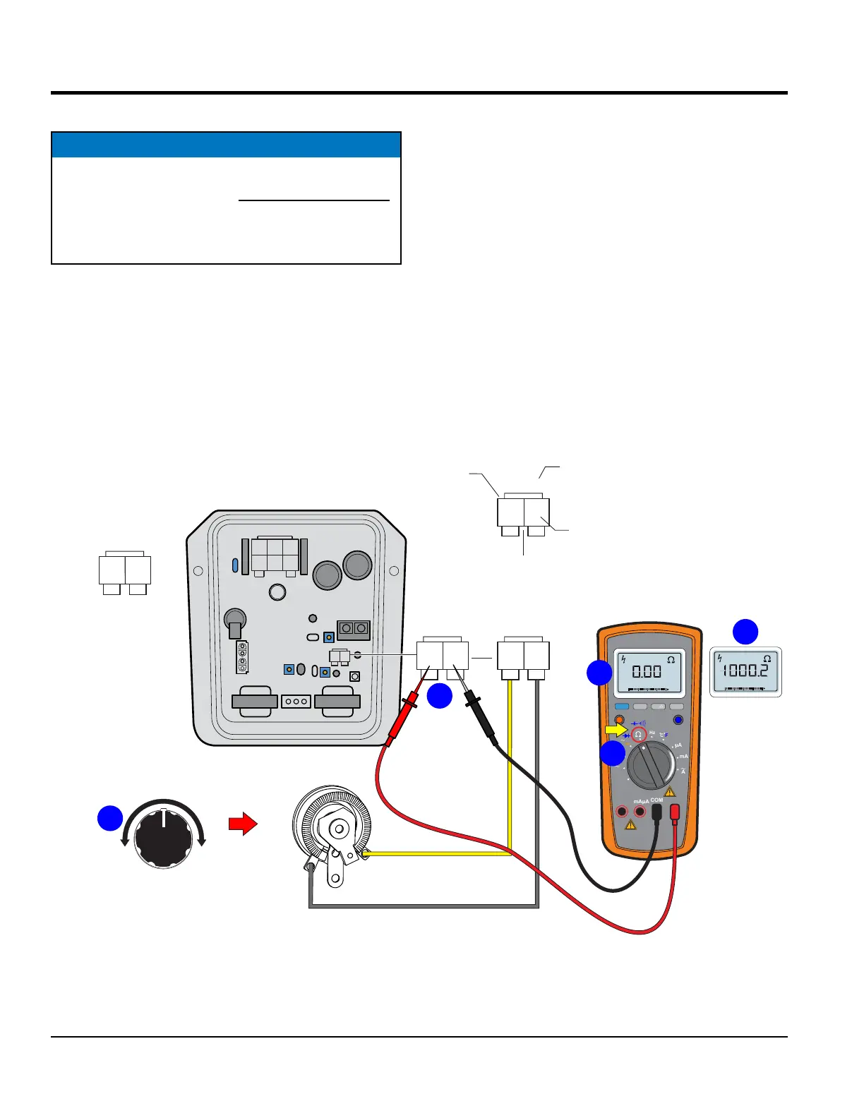
RHEOSTAT CHECK (CN4)
Symptom: AC voltage output is half the normal value and
there is no response when adjusting rheostat.
Disconnect the CN14 plug from the CN4 receptacle on
the AVR and measure the resistance of the rheostat at
the connector plug.
NOTICE
Before performing the resistance check, the CN14
connector plug (Figure 53) must be disconnected
from the CN4 receptacle on the AVR. If the reading
indicates an open circuit or incorrect reading replace
the rheostat.
Set the multimeter selection dial to to the W position as
shown in Figure 53A.
Place the multimeter leads between pins 1 and 3 on the
CN14 connector plug (Figure 53B). Turn the voltage control
knob (Figure 53C) fully counterclockwise. The multimeter
should read zero ohms (Figure 53D).
Next, turn the knob slowly until the knob is fully clockwise
and the multimeter should read about 1000 ohms
(Figure 53E).
Figure 53. Rheostat Resistance Check
DECREASE
INCREASE
2
1
A J C
DKB
3
CN1
CN2
CN3
CN4
RECEPTACLE
2 1
13
1 2
31
CN14
PLUG
PIN NO.
WIRE
LABEL
REAR VIEW
WIRE SIDE
CN14
2 1
13
CN15
3
1
1 2
31
YELLOW
GRAY
1000Ω0Ω
VOLTAGE REGULATOR
CONTROL KNOB
(RHEOSTAT)
2 1
13
CN4
MULTIMETER
RANGE
MIN MAX
MULTIMETER
Auto0 600
OFF
Hz
C
A
mA
uA
F
V
Hz
V
mV
Hz %REL
HOLD/LIGHT
10 A
MAX
mAµA
COM
A
Auto0 600
D
E
B
AVR
RHEOSTAT
(REAR VIEW)
C
FRONT VIEW
AUTOMATIC VOLTAGE REGULATOR