GENERATOR SERVICE AND TROUBLESHOOTING MANUAL — REV. #0 (08/29/23) — PAGE 11
Stationary Exciter Field
The stationary exciter eld (Ex Fg) Figure 3 receives
DC current from the automatic voltage regulator (AVR)
to create an electromagnetic field that produces the
magnetic ux required to induce an AC voltage into the
rotating exciter armature. The strength of the magnetic
eld is controlled by the amount of DC current received
from the AVR.
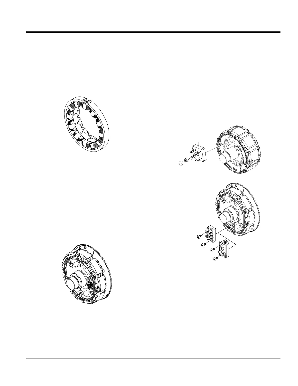
Figure 3. Stationary Exciter Field
Exciter Armature
The exciter armature (Ex Ar) Figure 4 is a three-phase
armature and it rotates inside the exciter eld and cuts
through the magnetic lines of ux created by the exciter eld
which through magnetic induction induces an AC voltage
into the exciter armature windings.
The magnitude of the induced voltage is controlled by
the strength of the exciter’s magnetic eld and how fast
the exciter armature cuts through the lines of ux (Engine
speed).
Figure 4. Exciter Armature
GENERATOR THEORY
Rectiers (Re)
Rectiers (Figure 5) are mounted on the end of the rotor
plate. The rectiers vary between models, as exampl the
DCA45-70 utilize three single-phase half wave rectiers.
DCA125-150 utilize two full wave three-phase rectiers
connected in parallel.
The rectiers receive three-phase AC voltage from the
exciter armature and converts the AC to DC voltage which
is sent to the main eld to create a rotating electromagnetic
eld.
Figure 5. Rectiers
CONVERTS AC TO DC
RECTIFIER
DCA 6-70
DA7
GENERATORS
HALF-WAVE
RECTIFIER
RECTIFIER
DCA 125-600
GENERATORS
FULL-WAVE
RECTIFIER