PAGE 12 — GENERATOR SERVICE AND TROUBLESHOOTING MANUAL — REV. #0 (08/29/23)
GENERATOR THEORY
Rotating Main Field
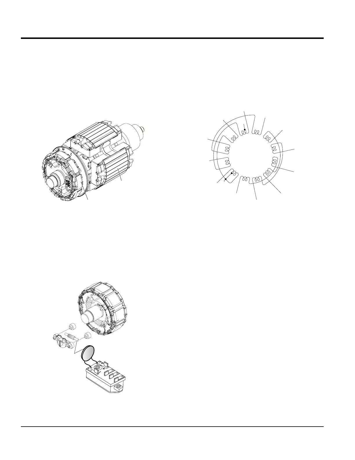
The rotating main eld (Fg) Figure 6, is a 4-pole rotating
eld, it rotates inside of the armature windings located
inside of the armature housing. The main eld receives it
DC voltage from the rectiers to create a magnetic eld.
The stationary armature windings cut through the rotating
magnetic lines of ux which induces an AC voltage into the
armature and open delta windings.
Figure 6. Rotating Main Field
Surge Absorber
The surge absorber Figure 7, is a metal oxide varistor
connected in parallel with the main eld and its purpose is
to dissipate transient voltage spikes caused from sudden
load changes to prevent damage to eld windings, rectiers
and exciter armature windings.
Figure 7. Surge Absorber
ROTATING
MAIN FIELD
EXCITER
ARMATURE
U
V
W
ROTATING
SURGE
ABSORBER
EXCITER
ARMATURE
Armature
The armature (Ar) houses the main armature windings
(Figure 8) and auxiliary open delta windings. Utilizing
magnetic induction, the stationary armature windings cut
through magnetic lines of ux created by the rotating main
eld and induces alternating current (AC) into the armature
and open delta windings.
Figure 8. Main Armature Windings
The Armature for DCA25-150 generators is a 12 lead
armature, DCA180-600 generators use a 10 lead armature
which means there are six individual windings which allow
the unit to be connected in different voltage congurations.
DCA25-150 generators have a voltage selector switch
which allow the generator to be connected in three different
congurations, three-phase 240/139V Wye (Figure 9A),
480/277V Wye (Figure 9B), and single-phase 240/120V
Zig-Zag (Figure 9C).
DCA180-600 generators utilize buss bars to connect the
armature windings in two different voltage congurations
which are three-phase 480/277V high wye or 240/139V
low wye.
V2
Z1
X2
U1
Y1
X1
V1
Z2
Y2
U2 U3
V3
V3
W2
U1
V2
W3
U2
V1
W4
W3
V4
W1
U4