GENERATOR SERVICE AND TROUBLESHOOTING MANUAL — REV. #0 (08/29/23) — PAGE 13
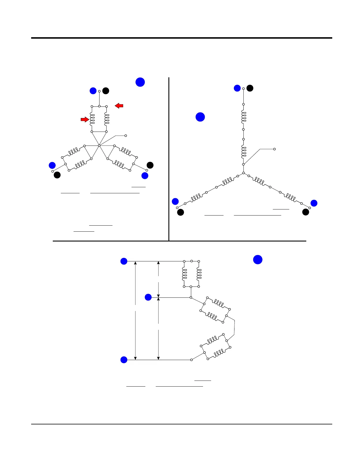
Figure 9 represents 3Ø high/low Wye wiring applications and 1Ø applications. Reference Figure 35 for armature windings
and voltage selector switch (VSS) terminal callouts.
Figure 9. 3Ø Wye and 1Ø Zig Zag Diagrams
V2
L1 U
U1
X1
U2
X2
Y2
N
V1
V
L2
Y1
L3
W
W1
Z1
W2
Z2
LO
U1
L1
U2
X1
X2
Z2
W2
W1
V1
Y1
V2
Y2
Z1
STATOR
WINDINGS
U1
L1 U
U2
X1
X2
L2
V
L3
W
Y1
V1
Y2
V2
Z2
W2
W1
VSS
TERMINALS
Z1
N
L2
240 VAC
120 VAC
120 VAC
Parallel connections produce lower
voltage but amperage is higher
139 VAC phase to neutral
240 VAC phase to phase
3-Phase Low Wye
N
LO
Series connections produce higher
voltage but amperage is lower
Single-Phase Zig-Zag
277 VAC phase to neutral
480 VAC phase to phase
3-Phase High Wye
DCA6 ~ DCA150 Generators
TLG8 ~ DCA400 Generators
Series connections produce higher
voltage but amperage is lower
DCA25 ~ DCA600 Generators
DCA10, DCA15, DCA20 and DCA36
generators are excluded from the
3-phase low wye application.
NOTE:
B
A
Single-Phase 240/120 VAC
C
GENERATOR THEORY