GENERATOR SERVICE AND TROUBLESHOOTING MANUAL — REV. #0 (08/29/23) — PAGE 87
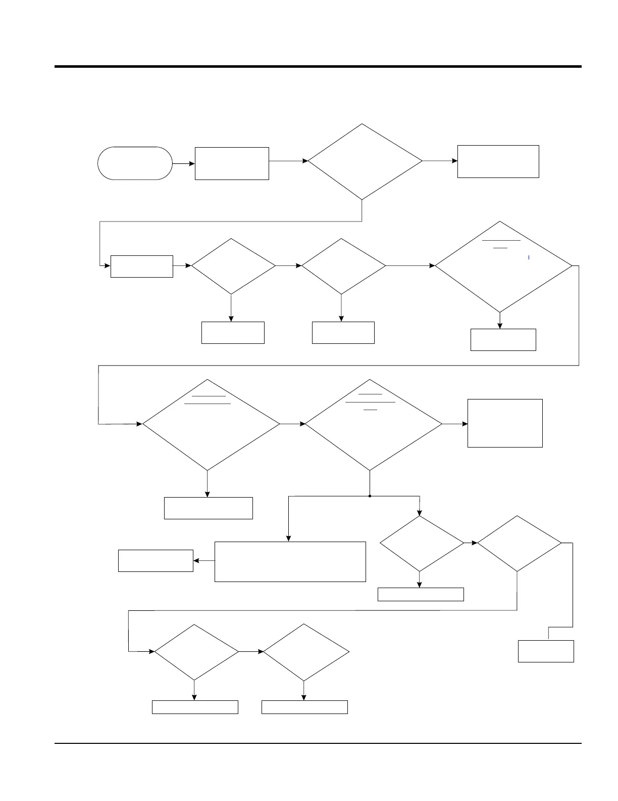
TROUBLESHOOTING FLOWCHARTS
N o ro V rise o t e coltage very ise ldr lit l u
insu ion rea n indicate a ow t e exci elat b kd n h ti r
nfie d ry vo li d. Sh il iwhen ba age s ap utte t p e ut tl
p rf t xoff a d e o m on est on e citer n r uins lat field.i
ion dR o sula est a s.efer t t for etin t il
Replace or refurbish main
stator (armature)
With Rotating
Rectifier disconnected
test Exciter
Armature
Replace exciter field
and retest unit
With rectifier
disconnected
test main
field
Replace or refurbish rotor
Disconnect
stator leads from
voltage selector switch
Refer to stator
test section
PASS
FAIL
Replace or refurbish stator
Replace or
refurbish rotor
PASS
Set Voltage Selector
Switch or Bus Bars to
240 Volts Three Phase
Verify no voltage
output. Start unit and
run at 1800 RPM. Verify
output voltage at top of circuit
breaker with multimeter.
Phase to Phase and
Phase to Neutral.
FAIL
Inspect and troubleshoot
voltmeter on control
panel/digital controller
With unit OFF, inspect
for loose damage or
burnt wiring
Check all AVR plug
connections
Check AVR fuse
Check rheostat (VR)
circuit
FAIL
Replace fuse
PASS
FAIL
Replace Rheostat
and retest
PASS
Disconnect 6 pin connector
from CN1 receptacle on AVR.
Measure resistance at pins
Test exciter
field.
Reference Table 6
J and K on CN5 plug.
for correct
resistance
FAIL
Repair wiring or
replace Exciter Field
PASS
PASS
Test Open
Delta Winding.
Disconnect 6 pin connector
fr AVom CN1 receptacle on R.
Measure resistance at pins
AB, CD, DA and BC on CN5 plug
Reference Table 6
for correct
resistance
FAIL
Manual
Excitation Field
Test
Disconnect 6 pin connector
fr AVom CN1 receptacle on R.
Connect 12 VDC battery to pins
J and K on CN5 plug
Reference Table 7
for correct
voltage
PASS PASS
If AC output voltage
meets values as
referenced in Table 7
Indicates faulty AVR,
Replace AVR and
retest unit.
FAIL
FAIL
NO VOLTAGE
PASS
FAIL
PASS
FAIL
PASS
FAIL
Replace rotating rectifier.
Test Rotating
Rectifier. Reference
Rotating Rectifier
test section.