Video Grabber User Manual - v. 1.19 (FW 1.29)
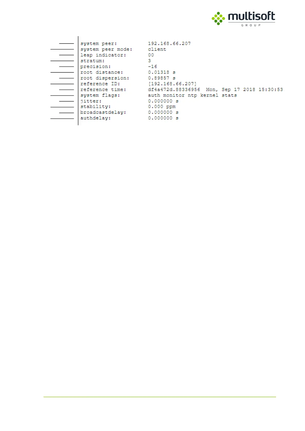
Figure 13: Detailed information on currently chosen peer
1. system peer – the peer that has been chosen and is used as a clock reference (marked with *
in the table above).
2. system peer mode – Video Grabber’s mode of ntp operation.
3. leap indicator – two-bit code warning of an impending leap second that is to be
inserted/deleted in the last minute of the current day. The coding is as follows:
a. 00 – no warning,
b. 01 – last minute of current day will have 61 seconds,
c. 10 – last minute of current day will have 59 seconds,
d. 11 – alarm condition (clock is not synchronized).
4. stratum – stratum level of the system peer. Represents the distance from the reference clock
e.g. stratum 0 is atomic clock, stratum 1 is a clock that syncs to that atomic clock etc.
5. precision – precision of the Video Grabber’s clock, in seconds to the nearest power of two.
6. root distance – maximum error of the clock offset estimate due to all causes as long as the
source remains reachable.
7. root dispersion – maximum error relative to the current system peer.
8. reference ID – the interpretation of this field depends on the stratum of current system peer.
For stratum 2 and higher (most common in case of Video Grabber) it is the IP address of the
system peer.
9. reference time – time currently set on the Video Grabber
10. system flags – list of currently enabled ntp server options. Defined in firmware, cannot be
changed by user.
a. auth – new associations or remote configuration commands require cryptographic
authentication
b. monitor – monitoring of ntp is enabled
c. ntp – local clock can be adjusted by NTP
d. kernel – precision-time kernel support
e. stats – statistics facility is enabled
11. jitter – measurement of the variance in latency on the network.
12. stability – residual frequency error remaining after the system frequency correction is
applied. After device starts this value should decrease to 0.1-0.01 ppm over time. If it
remains high (e.g. >1 ppm) then it may indicate a problem with a local clock.