Video Grabber User Manual - v. 1.19 (FW 1.29)
2.3. OLED screen
By default OLED screen displays basic status information of the device. User can configure it to also
show a view with NTP status. In such case both ‘views’ are shown at intervals (See 4.2.3 on p. 36 for
details on OLED configuration and 4.1.3 on p. 16 for details on NTP parameters).
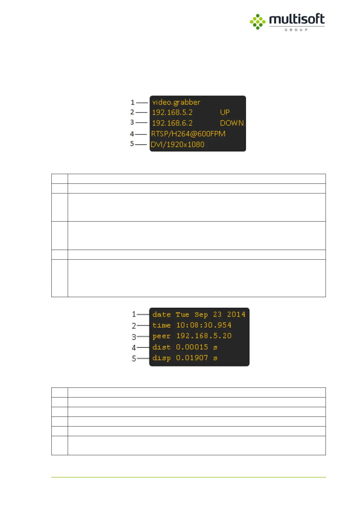
Figure 3: Device status screen
IP address set on the first network interface (LAN1) along with the link status:
UP – link is active
DOWN – link is inactive
IP address set on the second network interface (LAN2) along with the link status:
UP – link is active
DOWN – link is inactive
Currently used Output settings displayed in format: protocol / format @ capture frequency
Parameters of signal connected to the device displayed in format: signal type / resolution
Possible signal types:
VGA – analogue
DVI – digital
Figure 4: NTP status screen
Current date set on the Video Grabber
Current time set on the Video Grabber
IP address of currently used NTP server
Root distance to the currently used NTP server
Dispersion – potential clock offset error due to the maximum uncorrected system clock
frequency error