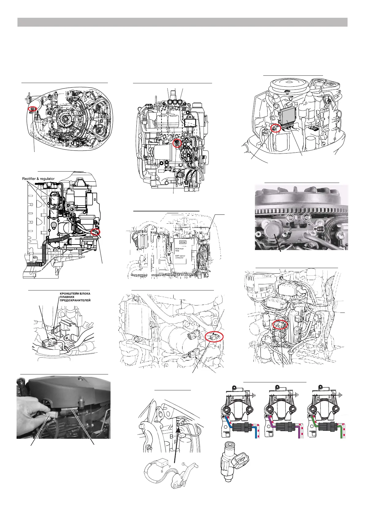
3). Possible locations of connectors and sensors
To connect the Multitronics CL-950E to the diagnostic connector of the engine, refer to the manufacturer's technical
documentation or to a technician experienced with these types of engines.
As a rule the diagnostic connector is located next to the engine control unit (ECU) under a protective cover against
moisture and dirt.
The schemes below show the locations of diagnostic connectors and sensors for some types of engines from various
manufacturers.
fuses
3-pin diagnostic
connector
Yamaha F(T)50 / F(T)60
engine control
unit
3-pin diagnostic
connector
Yamaha F(L)150A
3-pin diagnostic connector
Yamaha (L)F200 / (L)F225
diagnostic connector
Suzuki DF200/225/250
diagnostic
connector
Suzuki DF40 / DF50
diagnostic
connector
Suzuki DF300
diagnostic
connector
Honda BF40D / BF50D
diagnostic connector
(red)
Honda BF200A / BF225A
Honda BF135A / BF150A
diagnostic connector (red)
-10-
diagnostic connector protective cap
Evinrude E-TEC 75, 90 HP
The "trim" wire must be connected to the signal wire (see the
electrical diagram for the engine. In most cases you can determine
the proper wire using a tester: one of the wires is the ground, on
the second (signal) the voltage varies depending on the position of
the engine. The example on the right demonstrates that B is the
ground (black) and P is the signal (pink).
Connect the "injection plug" wire to the signal
wire (see the electrical diagram for the engine).
As a rule it is possible to determine the signal
wire by color as each plug is assigned to its own
color whereas the common wire has the same
color for all plugs. In the example diagram above
the signal wires are blue, purple or green whilst
the white-red wire is the ground.
trim sensor
petrol injection plug