2.4.3. Building your NMEA2000 network
Multitronics CL-950E takes readings of parameters via the diagnostic line of the engine and transmits the processed data
to the NMEA2000 bus allowing to display this data on the screens of other devices (for example, a chartplotter) or to
create a network of several trip computers and ensure their simultaneous operation.
This technology gives advantage of integrating into the NMEA2000 network even those engines that do not support the
NMEA 2000 format (except J1939 protocol). Parameters of the engine operation of your water vehicle can be displayed
on a chartplotter.
To activate data transition into the NMEA2000 network proceed the following steps after Multitronics CL-950E has been
mounted and connected:
1. Turn on the chartplotter and wait till it is booted up.
2. Make to following changes to the settings of the device: “Settings display-Control-Conversion to NMEA-ON”
3. Turn off the ignition and wait till the screen of the Multitronics CL-950E is off then turn on the ignition (start the engine)
4. Select the engine parameters on the chartplotter according to its manual instructions.
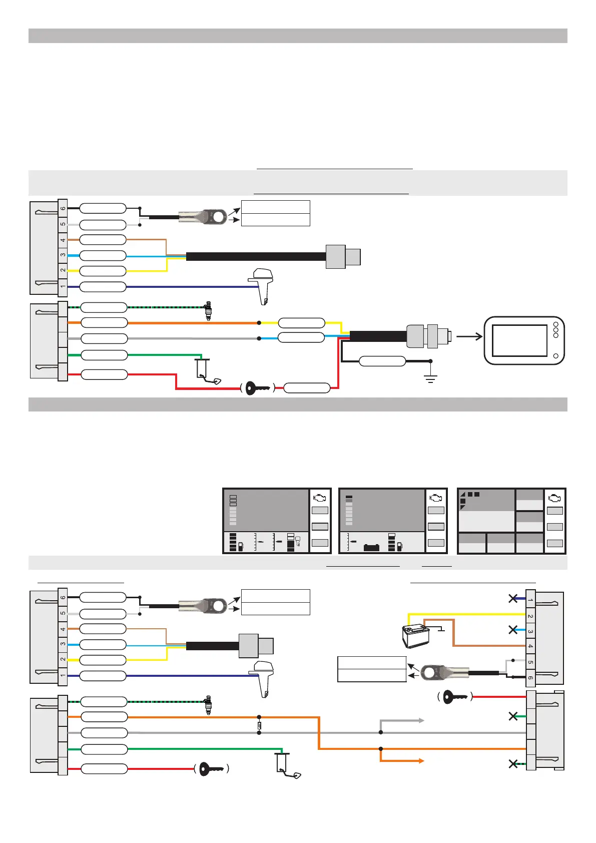
Connection to engines without NMEA2000 and data transmission to the chartplotter
(on example of Yamaha, Suzuki or Honda cables)
to chartplotter
2150 rpm
3,8 l/h
67 km/h
18 l
79 ºС
to trim sensor
(trim)
temperature sensor (option)
to diagnostic connector
on motor
air temperature
water temperature
purple
yellow
blue
brown
+12V
K-line
ground
white
black
7 8 9 10 11
to ignition
key
to fuel sensor
red
green
grey
orange
black-green
to injection plug (if desired)
blue
yellow
ground
red
black
ignition lock
female connectro
Multitronics NMEA2000-F
2.4.4. Building the NMEA2000 network with several computers
When The Multitronics CL-950E is specified as the main computer it reads parameters from the engine
diagnostic line and transmits the processed data to the NMEA 2000 bus, which allows this date to be displayed
on screens of other trip computers thus creating a network of several trip computers and ensuring their
simultaneous operation.
Such parallel operation can be build up by one set of cables which connects the main trip computer to the
engine, other connections can be made with ordinary wires.
illustration of connection of several computers via Yamaha, Suzuki and Honda cables
R1=120 ohm *
* When connecting several trip computers to each other, installation of at least one resistor R1 = 120 ohm is mandatory
otherwise computers will not work.
to engine trim sensor
(trim)
temperature sensor (option)
to diagnostic connector
on motor
air temperature
water temperature
purple
yellow
blue
brown
+12V
K-line
ground
white
black
7 8 9 10 11
to ignition
lock
to fuel sensor
red
green
grey
orange
black-green
to injection (if desired)
temperature sensor (option)
air temperature
water temperature
not used
not used
7 8 9 10 11
7 8 9 10 11
to ignition
lock
not used
not used
CL-950E - main CL-950E - additional 1
+
battery
ground
+12V
CAN-low
CAN-high
CAN-low
CAN-high
CAN-low
CAN-high
-8-
20
10
-10
Tri
3
-3
4,8
Fuel, l/h
This example illustrates screens of
several trip computers built into one
network and showing the following
information:
speed, rpm, trim, roll, trim, fuel residue, engine and
water temperature, voltage, time, fuel consumption
71
204
13.2 41 501
Т cyl.
Cost/Trip
Currency
Voltage
V
Fuel left
l
Mileage progn.
km
60
Speed
km/h
2560
rpm
18:21
3
-3
13.2V
Main СL-950Additional 1 СL-950 Additional 2 СL-950
CAN-low
CL-950E Additional 2
CAN-high
CL-950E Additional 2
Т cyl.
71
trim
7
rpm
2560
Т cyl.
71
trim
7
rpm
2560
Т cyl.
71
trim
7
rpm
2560
 Loading...