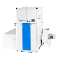
A
Figure 3.10 A : M8 screw seen from underneath.
D
Figure 3.11 D: Cover plates
4. Tighten the four M 8 screws (A) to compress the seals.
5. Fasten the two cover plates (D) with pop rive ts (4 x 10 mm) .
6. Unscrew the lifting eye bolts from the top box to prevent lifting of the assem bled unit.
7. Move the unit to its final position o n the site using a fork lift or pallet loader, before installing the fans
and filter box(es).
8. Install the process fan and process filter box(es) to the rotor box.
NOTE!
Standarddeliveryincludes one process filter box.
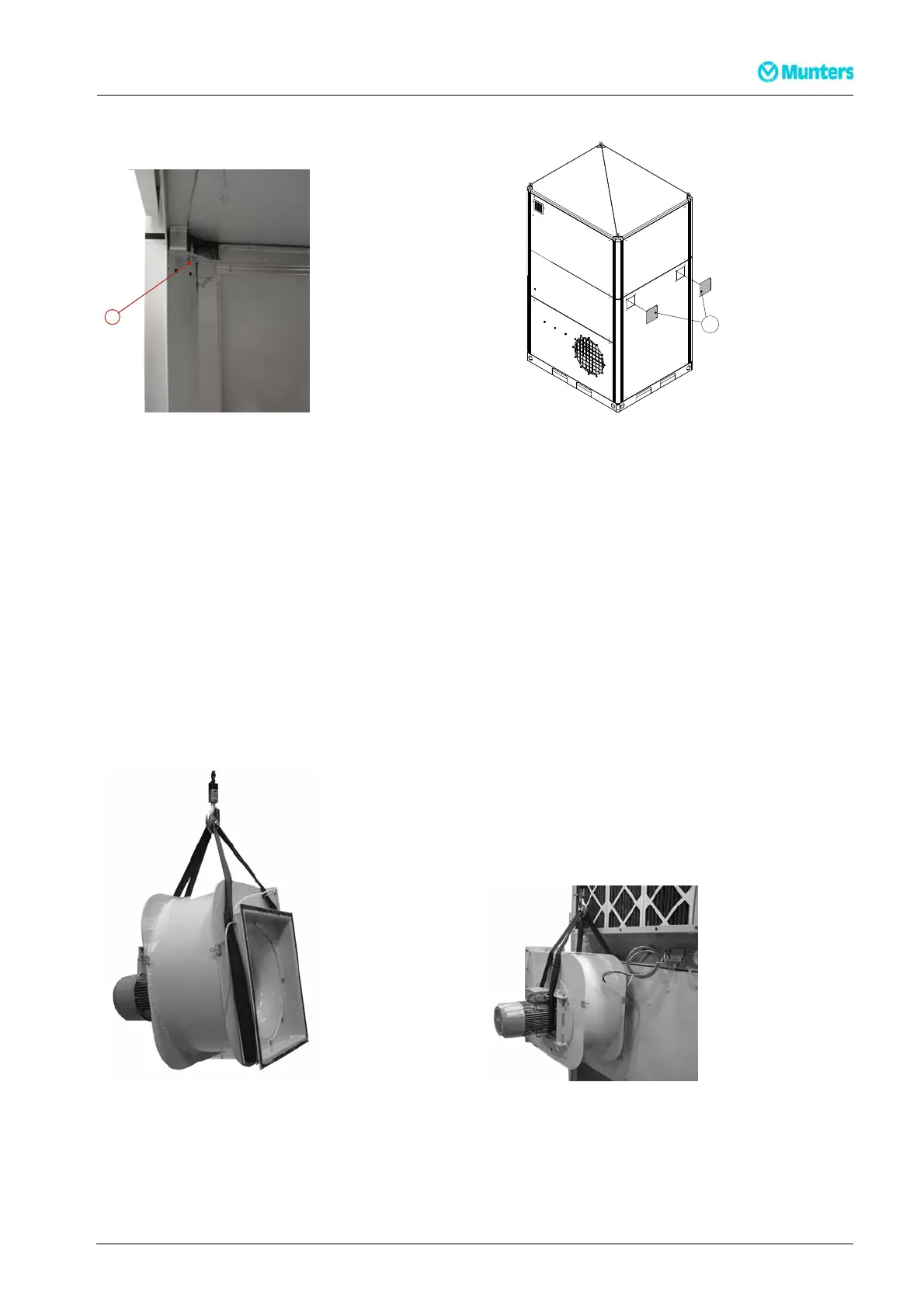
9. Attach a sling to the reactivation fan according to Figure 3.12 and lift the fan into position on the rotor
box.
10. Tighten the screws holding the fan before removing the sling.
Figure 3.12 Lifting the reacti vation fan Figure 3.13 Reactivation fan lifted into position
190TEN–106 5–J1408
Installation
15