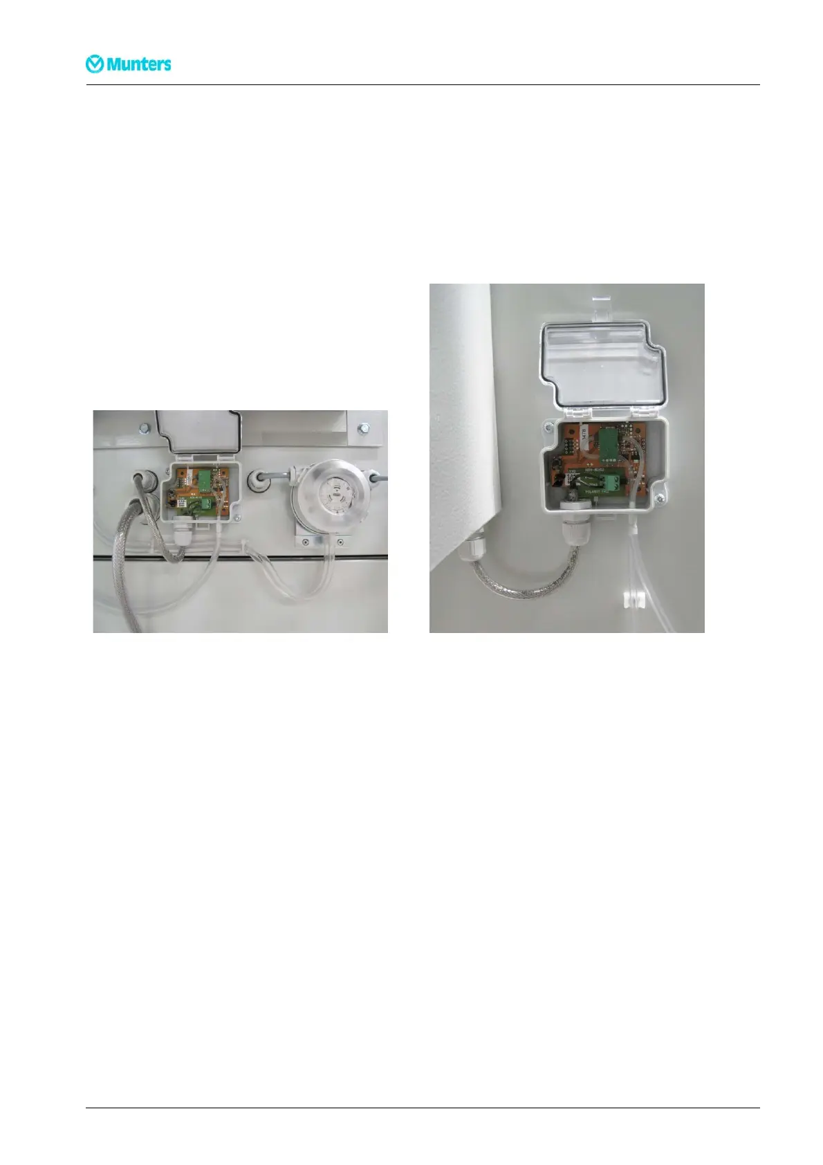
6. Connect the DPT (Differential Pre ssure Transmitter) for the reactivation fan. T he bottom side of the
DPT is marked with plus (+) and minus (-) at the two c onnections.
– Connect the tube from the fan duct (before impeller) to plus ( +).
– Connect the tube from the fan cone (impeller) t o minus (-).
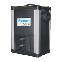
7. Connect the DPT for the process fan.
– Connect the tube from the fan duct (before impeller) to plus ( +).
– Connect the tube from the fan cone (impeller) t o minus (-).
Figure 3.22 Connection for DPT (Reacti vation fan) Figure 3.23 Connection for DPT (Processfan)
18
Installation
190TEN–106 5–J 1408